Splines and Deformation
Introduction to splines and deformation
The Rig Tools deformer is in some ways similar to Maya’s Smooth Skin deformer. Both have joints as inputs and influences that can be weight-painted. But in order to provide smooth and reliable spline deformation, Rig Tools does things a bit differently.
Rig Tools joints don’t directly input into the deformer like a Smooth Skin deformer. Instead, Rig Tools joints and bone CVs output to a Rig Tools spline. The Rig Tools spline runs through the joints and bone CVs of a joint chain and outputs a deform field. Each deform field then outputs to the Rig Tools deformer as an individual influence. Figure 1.
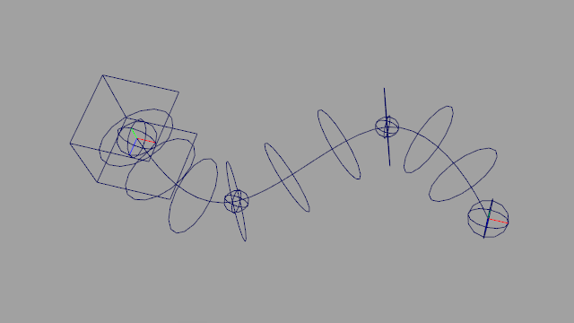
Figure 1
The deform field adjusts the positions of mesh vertices so that they “spread” along the length of the spline, providing excellent deformation in areas of high curvature, maintaining volume and creating fair curves in the silhouette of the mesh. It also reduces self-intersection and eliminates candy-wrappering, as long as the mesh is sufficiently dense to support the required twist. Figure 2.
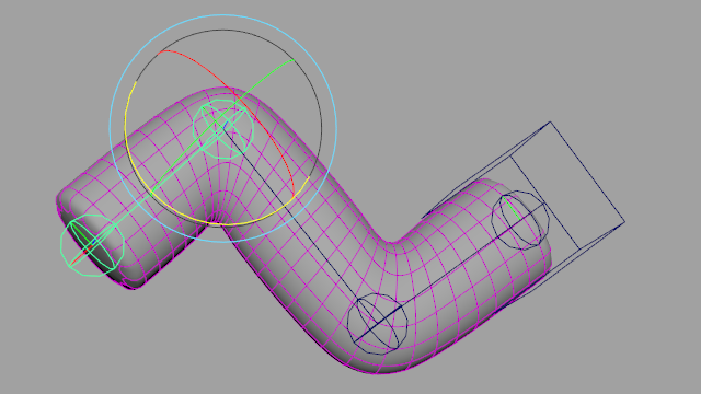
Figure 2
A rigid influence added to the deformer doesn’t have a Rig Tools spline and is treated as a simple transform, very similar to a standard smooth skin influence.
Binding meshes to a Rig Tools spline
To bind meshes to influences using the Contour deformer, select one or more influences and one or more meshes, and choose Rig Tools ► Deform ► Bind Mesh to Influences from the menu. Influences can be Contour joint sockets or non-Contour transforms, but cannot be Maya joints. The order of the selection doesn’t matter—each mesh will be bound to all influences.
A new deformer will be created for your meshes, with a Rig Tools spline influence for each joint socket and a rigid influence for each transform that is not a joint socket. Contour will only bind meshes that are actually selected, rather than binding meshes that are descendants of the selected nodes. Transforms that have more than one mesh shape cannot be bound.
The menu item Rig Tools ► Deform ► Bind Mesh to Influences and Descendant Contour Chains will not only bind a mesh to the selected influences, but will bind the mesh to any Contour joint chains that are descendants of those influences. This allows binding all of the joint chains of an entire character at once, if they’re in a single hierarchy.
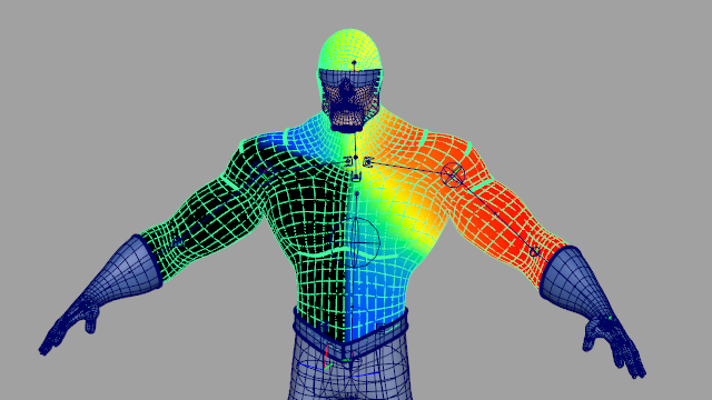
Figure 3
Once your mesh is bound to a Rig Tools deformer, you can add new joint chains or rigid influences with Rig Tools ► Deform ► Add Influences. If a transform that is not a joint socket is selected, the influence added will be a rigid influence. You can use this menu item to add meshes as rigid influences as well.
The deformation produced by the Rig Tools deformer generally looks good even immediately after binding. Test out the effect by moving some of the Rig Tools joints around. If the spline radius was set correctly when laying out the joint chains, areas like elbows and knees may need no further adjustment. Figure 4.
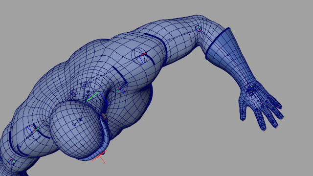
Figure 4
Unbinding Meshes
To unbind one or more meshes that have a Rig Tools deformer, select the meshes and then pick Rig Tools ► Deform ► Unbind Meshes. This will delete the Rig Tools deformer of the selected meshes.
Rebind Mode
In cases where adjustment is needed, Rig Tools makes it easy to rebind the mesh without losing any weight painting data. Rebind Mode is used to adjust the position of rig elements after the mesh has been bound. Rebind mode can be entered by choosing Rig Tools ► Deform ► Rebind Mode ► Enter Rebind Mode.
Once Rebind Mode has been entered, rig deformation is temporarily disabled. Rig elements can be adjusted now. The preferred way of adjusting Rig Tools joint chains is with the Rig Tools Joint Tool. Using this tool will allow joints to be moved without affecting their children, and will preserve the fully buffered status of the joints. Figure 5.
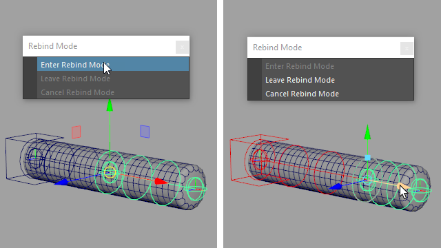
Figure 5
Rebind Mode is not a tool, it is a mode, so other tools can be used to manipulate rig elements as well. Bear in mind the potential effects on the final transform values however.
When satisfied with the position of the joints, exit Rebind Mode with Rig Tools ► Deform ► Rebind Mode ► Leave Rebind Mode. The deformation is rebound using the current position of rig elements as the default position, and all other bind information is restored. Figure 5b.
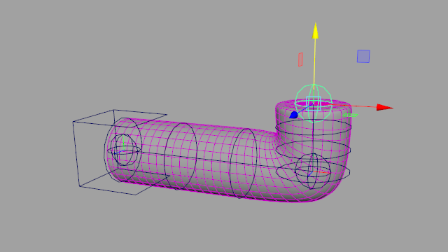
Figure 5b
If undesirable changes have been made to the rig, Rebind Mode can be exited without changing bind information. Rig Tools ► Deform ► Rebind Mode ► Cancel Rebind Mode will re-apply the bind information that was present when Rebind Mode was entered. Note: If the rig is not in the same position, this will cause the mesh to snap to the new pose.
Deformer Settings
The Rig Tools deformer provides great deformation right from bind, but it can be necessary to tweak settings to optimize appearance and performance. The attributes that affect deformeration are found in two places: attributes that affect only a single joint or bone CV are found on the joints and CVs themselves, while attributes that affect the entire Rig Tools spline are found on the joint socket.
Joint Radius
A joint’s Radius attribute controls the sharpness of the curvature of the spline as it nears that joint. A small radius will cause a sharp bend. As the radius is increased the joint will form a smoother, gentler bend. The radius can be increased until it includes adjacent joints or bone CVs; increasing it further has limited effect. Note that the Radius attribute found on joints is different from the Radius attribute found on Splines, which controls the distance from the spline at which the deformer produces the most pleasing deformation. Figure 6.
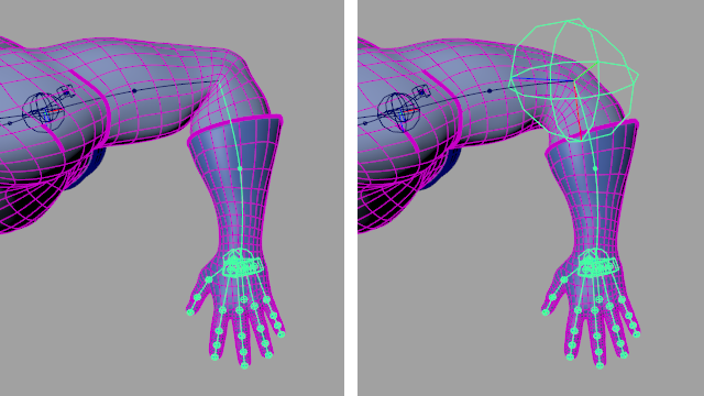
Figure 6
Twist and Inherit Twist
The Contour deformer calculates twist using Rotation Minimizing Frames, giving stable twist up to 180 degrees for the twist produced from the rotation of joints and the shape of the spline.
Each joint and bone CV has a Twist atrribute that can be used to directly control twist at its location along the spline. This twist is layered on top of twist produced by joint rotation, and is stable for arbitrarily large values of twist, including those above 180 degrees, as long as the mesh is dense enough to avoid candy-wrappering. Figure 7.
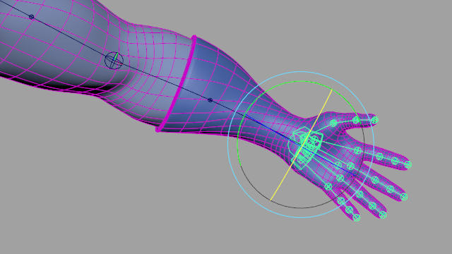
Figure 7
The Inherit Twist attribute found on joints controls where the twisting occurs when a joint is rotated. When a joint’s Inherit Twist attribute is set to true, the joint uses the rotation of the previous joint in the chain instead of its own rotation to calculate twist. This locks twist for things like shoulders, so that the twist occurs between the shoulder and elbow instead of in the shoulder itself. Figure 8
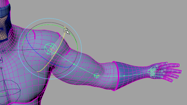
Figure 8
Bulge
Each joint and bone CV has a Bulge attribute that can be used to grow or shrink the mesh around the spline as it nears the joint or CV. Figure 9.
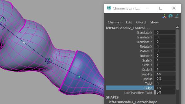
Figure 9
Spline-Wide Deformation Settings
Rig Tools provides high-level settings that adjust how an entire spline deforms a mesh. These attributes are found on the corresponding joint socket.
Spread: At sharp corners, naive spline-based deformers like wire deformers will have interpenetration or overlapping geometry. The Rig Tools deformer tries to avoid this by “pushing” the geometry out in the neighborhood of areas of high curvature. The Spread atytribute controls the strength of this effect. Too much spread can make the deformation imprecise and wiggly, while too little will cause stiff deformation that just follows the spline.
Values between 10 and 30 are usually the most useful. Very high values will produce increasingly smaller effect, but may incuir a substantial performace penalty. Figure 10.
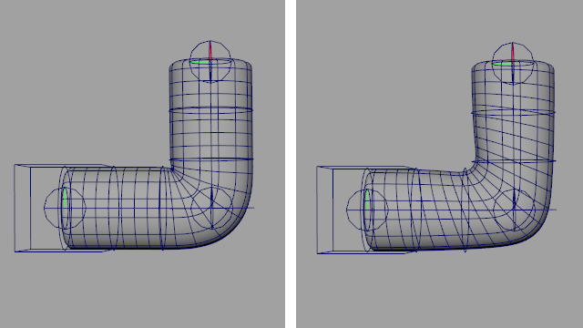
Figure 10
Radius: The Radius attribute—found on joint sockets, not joints—of the spline is the distance from the spline at which the deform field will produce the most pleasing results. Areas inside and outside of the radius will still be deformed, but results may become increasingly less appealing as geometry moves further from or closer to the spline. Small values, relative to the rough diamter of the mesh, will produce results that are similar to a wire deformer, while values that are too large will cause the deformation to become “faceted” on the outside of bends, and too smooth on the inside. Figure 11.
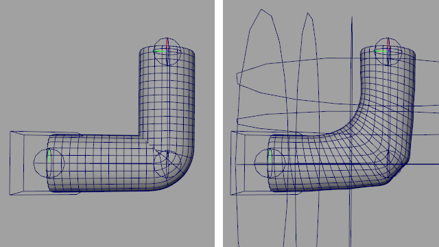
Figure 11
Longitudinal Density Factor: For performance reasons, Rig Tools uses a sampling method to approximate an ideal mathematical model of deformation. The Longitudinal Density Factor constrols density of the samples taken down the length of the spline. When deforming meshes that stretch but do not bend much, this value can be decreased to optimize performance. Alternatively, when geometry density is very high and curvature very large, it may be necessary to increase this value for greater accuracy at a cost to performance. LDF’s default value of 1 is a good balance for most cases, and this value can usually be left at the default.
The Spread attribute relies on the LDF to calculate how far to push geometry. Changing the LDF will likely also require a readjustment of the Spread value to achieve the same results.
Radial samples: The radial version of the LDF, this controls the density of the field around the spline. This value can be increased to improve accuracy for high density meshes. In particular, very rapid rotation of a mesh around a spline can cause instability in the results of deformation when this value is at the default, and increasing it will sove this.
Radial samples is set to 8 by default. Lowering the samples below 8 is possible but not recommended. Increasing the samples above 8 will improve accuracy but at a high performance cost. Like the LDF, the default value is usually correct.
Volume Gain: Volume Gain controls how much the inner surface of the mesh at a sharp bend in the spline smooths itself out to avoid “pocketing” and volume loss. Volume Gain pushes vertices away from the spline in the neighborhood of an acute bendin the spline, while Spread moves geometry along the spline.
The Volume Gain attribute controls the strength of this effect. Usually values between 20 and 60 produce the best results. The default value of 40 produces good results for most geometry. Figure 12.
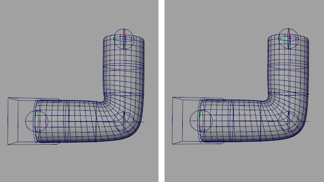
Figure 12
Volume Gain Spread: This attribute controls how wide an area up and down the spline the effect of Volume Gain covers. Larger values will result in more volume and softer inside corners. Figure 13.
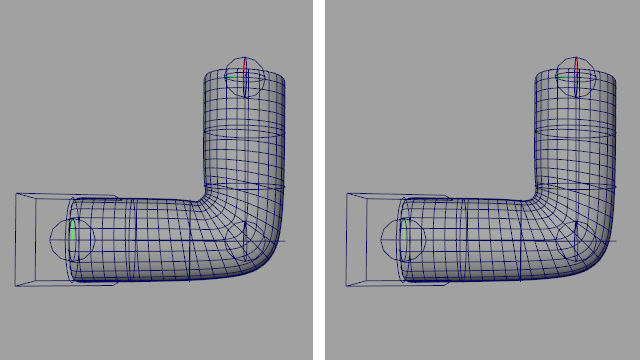
Figure 13
Twist interpolation Type: Sets the method used to interpolate twist along the spline. Spline interpolation eases in and out of the joints, concentrating more of the twist in the middle of the bone. Linear distributes the twist evenly. Some meshes benefit from a more even twist. Figure 14.
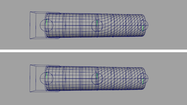
Figure 14
Influences and Weights
Using rigid influences
The Rig Tools deformer provides the most value in areas where the desired deformation is smooth and soft, such as arms, legs, spines and tails. However, there are some areas where the distribution of bending and spreading Rig Tools provides is undesirable. In these areas, adding rigid influences to your deformer gives you explicit control over how an area will deform. The rigid influence works exactly like a standard smooth skin influence, and can be adjusted with painting or the Rig Tools Component Editor. Figure 15.
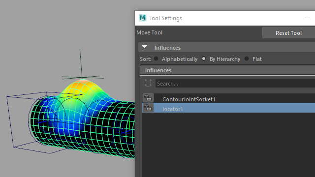
Figure 15
Areas where rigid influences are frequently used include heads, small influences like ears, buttons, armor, and other rigid parts of clothing. In some cases, like the bottoms of the feet, rigid influences can be used on one side of a spline to limit the spread and bend of the deformer only to areas where it benefits you.
Rigid influences are frequently parented to a Rig Tools Joint or constrained using the Rig Tools deform field constraint (below). Either of these options allows a Rig Tools joint chain to be used for animation without any additional layers of control.
Painting weights on the Rig Tools deformer
Painting weights on the Rig Tools deformer has been designed to be very similar to using the Maya interface. There is a list of influences (each either a deform field or a rigid influence) and each can be selected in order to perform the usual weight painting operations. The deformer will use a linear blend between the influences. Figure 16.
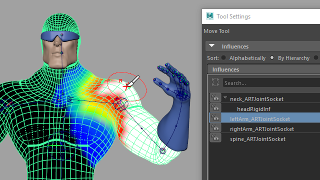
Figure 16
There are a few notable differences in how you will wanto to paint weights for a Rig Tools deformer, though. The first is that since most of the influences are usually entire Rig Tools deform fields, and each deform field is driven by several joints, the number of influences you need to paint is drastically reduced. The areas that require painting are limited to where the deform fields overlap, and generally the number of influences affecting any given vertex is also reduced.
In part this reduction in complexity comes from an adjustment in how you think about areas that deform heavily. In order to gain the benefits of the Rig Tools deform field, areas that would usually be affected by many influences are better off weighted entirely to a single influence.
The inclusion of overshoot joints (in areas such as the hips), makes painting weights in this manner possible. The overshoot joint on a hip is rigged to move with the spine. Since the Rig Tools spline runs through this area with an appropriate curvature, the hip benefits fully from the spread and volume preserving aspects of the deform field, and provides easy adjustment of the appearance with the deformer attributes when much of the weight in the regions of highest deformation is given to the leg chain. Figure 17.
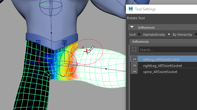
Figure 17
You may also note a small but pleasant difference when the weight painting tool tries to normalize weights after a paint stroke and can’t do so. Rather than normalize by including extraneous influences that had not previously affected the area, the deformer instead refuses to change the weight value if it can’t be normalized. This avoids situations where removing the last unlocked influence from a vertex would flood that point with a small value from every influence in the deformer, making weight values unpredictable.
Using the Rig Tools Component editor
Influence values can also be edited manually, using the Rig Tools Component Editor. To access this tool, choose Rig Tools ► Deform ► Component Editor, and select the vertices you wish to edit. The interface mirrors Mayas component editor and should be familiar. Select cells and enter the new values, select columns by clicking on the name of the influence and rows by the name of the vertex, etc. You can also lock and unlock influences, to prevent them being adjusted by normalization operations, by toggling the booleans in the top row.
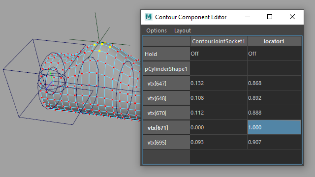
Figure 18
Copying and Mirroring weights
Weights can be mirrored within a mesh, mirrored between two meshes, and copied from one mesh to another in a straightforward manner. Both mirror and copy weights work by finding the closest point on a mesh in world space, so be sure to line your meshes up correctly before performing a mirror or copy.
To mirror influence weights within a mesh, select your mesh and choose Rig Tools ► Deform ► Mirror Weights. To mirror influence weights from one mesh to another, select the source mesh followed by the destination mesh, then choose Rig Tools ► Deform ► Mirror Weights.
Options for this tool include the axis to mirror across, the direction to mirror in, and method by which influences to be mirrored onto are associated with influences to be mirrored from. You can choose to associate influences by proximity or by name.
When mirroring weights by proximity, we first find the world-space position of each influence, mirrored across the mirror axis. We then match that influence with the influence whose world-space position is closest to that mirrored position. Note that this means that an influence can match itself when mirroring within a single mesh, as would be the case with, for instance, a spine. The world-space position of a Contour joint chain is the world-space position of its joint socket.
When mirroring weights by name the convention is that one side of your character is the right-hand side, and the other the left-hand side—which side is which is up to you. Mirroring will attempt to match influences with names that begin with “right_”, “right”, or “r_” with influences that begin with “left_”, “left” or “l_”, but are otherwise identical. The prefix matching is not case-sensitive (that is, “RIGHT” is treated as if it were “right”, etc.,) but the matching of the portion of the name after the prefix is. We do not limit prefix matching to prefixes of the same general form—that is, “right” will match “left_” or “l_”, as well as “left”. If this causes ambiguity—for instance if you have an influence named “right_hand” and influences named “left_hand” and “l_hand”—an error will be signalled. When mirroring within a single mesh, if an influence does not have a name with a prefix, or if no corresponding influence is found, the influence’s weights will be mirrored to itself. When mirroring weights from one mesh to another, all of the source mesh’s influences must have corresponding influences in the destination mesh, and source influences with no prefix must have an identically named destination influence.
To mirror weights onto just a portion of the mesh, create a Maya Set of vertices. Either select the Set to mirror weights within a single mesh, or select the source mesh and the Set to mirror weights from one mesh to another, and choose Rig Tools ► Deform ► Mirror weights from the menu.
To copy influence weights from one mesh to another, select the source mesh then the destination mesh and choose Rig Tools ► Deform ► Copy Weights. This tool has one option, which specifies how influences bound to the source mesh are associated with influences bound to the target mesh.
When copying weights by closest influence, each influence bound to the source mesh will be associated with the influence bound to the target mesh that is closest to it in world space. The world-space position of a Contour joint chain is the world-space position of its joint socket.
When copying weights by same influence, all influences bound to the source mesh must also be bound to the target mesh. Each influence will have its weights copied from the source mesh to the target mesh.
To copy influence weights onto a just a portion of a mesh, create a Maya Set of vertices. Select a mesh to copy from, and the set of vertices to copy to, and choose Rig Tools ► Deform ► Copy Weights.
Pruning weights
Rig Tools ► Deform ► Prune Small Weights will remove influences below the threshold from vertices, exactly like its Maya counterpart.
About Splines and Deform Fields
Every Rig Tools chain used in a deformer or constraint actually has two splines associated with it, an active spline and a bind spline. When animating, the two splines are compared and the difference between the two fields is what determines the deformation of the mesh. It’s possible to produce deformation by animating the bind spline as well, but every time the bind spline is changed, Rig Tools must rebind the mesh, which is a costly operation. Actions that would change the bind spline should be avoided when performance is an issue. By default, it is not connected to anything. Figure 19.
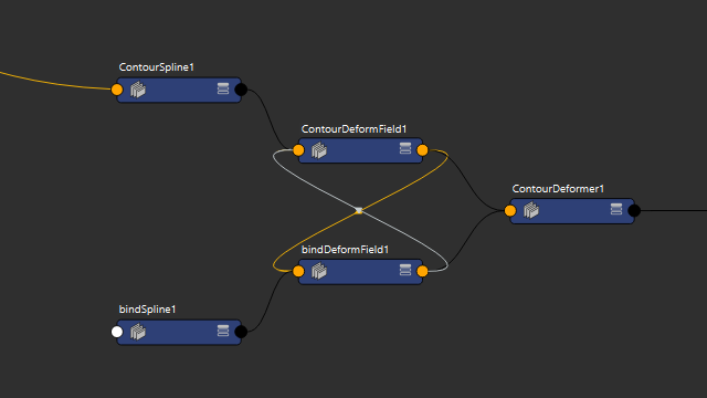
Figure 19
Rigid influences simply store a single transform matrix as their bind state, and do not have splines associated with them.
Scaling an entire Rig Tools spline
You can scale (including nonuniform scale) an entire spline and its deform field by scaling its joint socket. Figure 20.
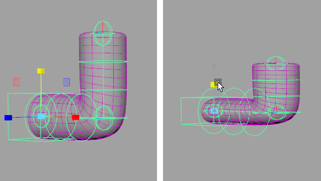
Figure 20
Driving Rig Tools Splines With Conventional Transforms
Our joints and bones are designed to output the information needed to drive Contour splines and deform fields, and our tools create the necessary connections automatically. Figure 21.
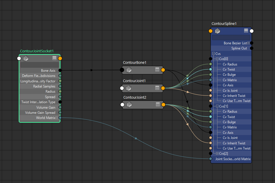
Figure 21
Advanced users may wish to use Contour’s splines and deformation without using Contour’s joints and bones. You can use conventional transforms to drive Contour splines by connecting the right attributes. Detailed instructions on how to do this are beyond the scope of this manual, but users experienced enough to want to create their own front-end to Contour deformation are likely to learn enough simply by looking at an existing Contour rig—we’ve tried to make the flow of data through Contour nodes as clean and easy to understand as possible.
If you’d like our assistance with setting up an alternative way of driving Contour deformation in your pipeline, please get in touch with us at business@notionalpipe.com