Contour Rig Tools 1.0 User Manual
Contents:
Acknowledgments
The release of Contour Rig Tools would not have been possible without the support of many. We’d particularly like to thank Janet Podell for her financial support, Nathaniel Stein and Morgan Robinson for assisting us with this manual, and the contributors to our IndieGoGo campaign, both for their financial assistance and for their patience.
IndieGoGo contributors
Vibranium
Platinum
Gold
Silver
Bronze
Foreword
Rigging deformable characters is an essential part of creating CG character animation. It’s also a notoriously ugly and finicky process, one that requires labor-intensive fiddling with vertex weights and large numbers of influences to achieve even minimally acceptable character deformation, or grappling with baroque auto-rigging systems. And having painstakingly rigged one character by ad-hoc means, you have to do it all over again for the next.
The product you’re about to use is the result of years of effort Tagore Smith, Brian Kendall, and I have put into answering the question “Is there some high-level problem that all these characters have in common? And could you solve that problem, instead of solving the problem of deforming a character from scratch every time?” It turns out that there is, and you can.
Most characters are made up of a bunch of more-or-less cylindrical shapes. Arms and legs are tubular. So are fingers, and torsos, and necks. So are deeper structures, like muscles. If you had a really good way of deforming tube-like shapes that was visually pleasing and offered high-level control over bend and twist behavior, you’d solve an awful lot of the problems that rigging TDs face on a daily basis. That’s exactly what Contour Rig Tools provides. What may at first seem like an alternative skeletal deformation system with magically perfect default deformation is actually built on top of a powerful spline-based deformation system that can deform any tube-like shape while preserving fair and even curvature in the mesh, even when deforming thick meshes with acute curvature. Contour’s spline-based bones provide a elegant and predictable “primitive” that you can build almost any kind of rigs out of simply and quickly.
While Contour Rig Tools hasn’t been available to the general public until now, I’ve been using it for production in various forms since the early 2010s, and it has completely changed the way I approach character deformation. This is perhaps best illustrated by one of the earliest production uses of Rig Tools. We had to animate a cartoon hand as part of a web advertisement, but had almost no schedule left in which to rig it. Getting decent deformation out of a hand that will be seen in close-up is normally a lot of work, especially if the hand will be called on to perform cartoony distortions. It’s the kind of last-minute addition to a project that gives technical directors fits.
This proved a perfect test-case for a pre-alpha version of Contour Rig Tools. I drew in some joints, adjusted their deformation settings, painted some simple weights to separate the fingers from each other, and in less than an hour the hand rig was done, and I was animating with it. While the rig was crude in some ways—just some FK joint chains—it was in other ways very advanced. It was infinitely stretchy, with perfect twist and bend behavior, and it could hit exaggerated poses that would break all but the most advanced conventional hand rigs. A task that without Rig Tools would at best have relied on clumsy half-measures, and at worst been impossible, was suddenly easy to perform, with a very high quality result.
Since then I’ve created far more advanced rigs using Contour, rigs that included complex control rigging and mixed Contour deformation with other deformation techniques to take advantage of the best qualities of each. I’ve rigged stretchy cartoon characters, semi-realistic characters with pseudo-muscle deformation, and even characters whose “deformation” was actually a large number of moving individual transforms. Regardless of their other qualities, these rigs still benefited from being built on top of a powerfully simple core. When you know your character’s limbs will automatically be able to handle almost any pose from the moment they’re bound, it frees you to focus on the aspects of the rig unique to a character or production, instead of becoming bogged down in the details of getting the rig to a basic level of quality.
When I encounter a complex rigging challenge under a tight deadline, I am no longer concerned. Contour Rig Tools has taken away my fear of rigging. I hope it will do the same for you.
–Raf Anzovin
Installation
Contour Rig Tools is available for Windows, macOS, and Linux. Rig Tools can be installed using an installer or manually on Windows and MacOS. Installation on Linux is manual only. Rig Tools binaries are available in three distributions, one per supported operating system.
Updates
Contour Rig Tools does not upgrade itself. To upgrade Rig Tools or change Rig Tools versions using the installer simply download and run the installer for the version you wish to switch to. To upgrade or change versions manually see the manual installation instructions.
Supported Maya versions
Each version of Contour Rig Tools generally supports the three most recent versions of Autodesk Maya available at the time of the Rig Tools version’s release. However, there is sometimes a period between the release of a new version of Maya and Rig Tools support for that version.
We only officially support the most recent update of each Maya version, but Contour will often work with older updates. However, Contour does not work in Maya 2023.0 and 2023.1. If you are running Maya 2023, please make sure you’ve updated to version 2023.2 or later.
Installing PyMel in Maya 2022 to 2025
Rig Tools requires PyMel when Maya is running in GUI mode. When Maya is running as a batch render or headless mode, PyMEL is not required in Contour version 1.0.9 and later. (This means you do not need to install PyMEL on a headless node in a render farm in order render scenes that have Contour nodes using Contour version 1.0.9 and later.)
Starting with Maya 2022, PyMEL is no longer included by default. If PyMEL is not installed, Contour will offer to install PyMEL for you when the plug-in is loaded on either Windows or macOS (if Maya is in GUI mode).
Installing PyMel in Maya 2026
As of the time of this writing, PyMEL has not been officially updated for Maya 2026. We are bundling an unofficial build of PyMEL by GitHub user iamsleepy that does support Maya 2026, and Contour will offer to install PyMEL for you when the plug-in is loaded and Maya is running on Windows or macOS in GUI mode.
If you need to install PyMEL manually, you can follow these instructions:
Download the .whl file for the latest release of PyMEL from this GitHub repository:
https://github.com/iamsleepy/pymel/releases.Open a terminal window and change to the current directory where mayapy is located.
Execute the following command:
mayapy install <path-to-pymel-whl>
wherepath-to-pymel-whlis the full path of the PyMEL .whl file you downloaded.
Running the installer under Windows
The Windows distribution unpacks to a single directory. In that directory will be an installer named “Install Contour Rig Tools for Windows.exe” and a directory named “InstallerData”. To begin installing Rig Tools run the installer. Note that the installer must be run from a directory containing the “InstallerData” directory.
Running the installer under macOS
The macOS distribution unpacks to a single directory, which contains an installer named “install.sh” that must be run from the Terminal. You can either navigate to the installer directory and execute the installer script from the command line, or perform the following steps:
Open Terminal (or your favorite terminal application)
Drag the file install.sh onto the Terminal window
Click the Terminal window to ensure it’s focused and then press return
Type your user account’s password when prompted, then follow the instructions in the Contour Rig Tools installer
Installing Contour Rig Tools using the installer
On running the installer an EULA dialog will be shown. After accepting the EULA a new window will be displayed, allowing you to select the versions of Maya for which you wish to install Rig Tools:
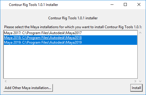
The installer will look in the standard Maya locations for your operating system when populating the list of versions it displays.
If you would like to install Rig Tools for a version of Maya installed in another location, click the “Add Other Maya Installation…” button. A directory selection dialog will be displayed. Select the directory of Maya version you wish to install Rig Tools for, and that location will be added to the Rig Tools installer’s version selection list.
Select the versions of Maya for which you would like to install Rig Tools and click the “Install” button to complete the installation.
Installing Contour Rig Tools manually under Windows
By installing Contour Rig Tools you agree that you have read and agree to the
terms of its license, which will be found in the InstallerData directory, in
a file named license.txt.
To install Contour Rig Tools you will need to copy three components to three locations on your hard drive. The three components are:
ContourRigTools.mll, the Maya pluginContourlib, the Rig Tools Python packageThe Rig Tools icons
ContourRigTools.mll will be found in InstallerData\<maya
version>\plug-ins\, where <maya-version> is the version of Maya you wish
to install Rig Tools for (e.g. 2019).
ContourRigTools.mll must be copied to a Maya plug-ins directory, or to a
directory included in the MAYA_PLUG_IN_PATH environment variable. The
default plug-ins directories are:
<maya-installation-directory>\bin\plug-ins\, where<maya-installation-directory>is the directory in which the version of Maya you wish to install Rig Tools for is installed<documents-directory>\maya\<maya-version>\plug-ins\, where<documents-directory>is your user account’s Windows Documents directory, and<maya-version>is the version of maya you are installing for (e.g. 2019)
The Rig Tools Python package will be found in the extracted archive at
InstallerData/<python-version>/site-packages/Contourlib/ where
<python-version> is the Python version you will be using (e.g. 2.7). Maya versions
prior to Maya 2022 use Python 2.7. Maya 2022 defaults to using Python 3.7, but can be
started using Python 2.7. To install the Rig Tools Python package, copy the entire
Contourlib directory to the appropriate Maya site-packages directory, or to a directory
included in the Maya PYTHONPATH environment variable. The default site-packages
directory for Maya is
<maya-installation-directory>\Python\Lib\site-packages\ in Maya versions prior to 2022,
and <maya-installation-directory>\Python<python-version>\Lib\site-packages\ in Maya 2022.
The Rig Tools icons will be found in the extracted archive at
InstallerData\icons\. To install them, copy each individual icon file in the
archive to a Maya icons directory, or to a directory included in the
XBMLANGPATH environment variable. The default icons directories are:
<maya-installation-directory>\icons\<documents-directory>\maya\<maya-version>\icons\
Maya environment variables can be set normally, or in the Maya.env file,
found in <documents-directory>\maya\<maya-version>\.
Once the above steps are completed, launch Maya, open the Windows >
Settings/Preferences > Plug-in Manager menu, find the ContourRigtools.mll
entry in the list of plug-ins, and click the “Loaded” and “Auto Load” checkboxes
to its right to load Contour Rig Tools.
Installing Contour Rig Tools manually under macOS
By installing Contour Rig Tools you agree that you have read and agree to the
terms of its license, which will be found in the InstallerData directory, in
a file named license.txt.
To install Contour Rig Tools you will need to copy three components to three locations on your hard drive. The three components are:
ContourRigTools.bundle, the Maya pluginContourlib, the Rig Tools Python packageThe Rig Tools icons
ContourRigTools.bundle will be found in
InstallerData/<maya-version>/plug-ins/, where <maya-version> corresponds
to the version of Maya you wish to install Rig Tools for (e.g. 2019).
ContourRigTools.bundle must be copied to a Maya plug-ins directory, or to a
directory included in the MAYA_PLUG_IN_PATH environment variable. The
default plug-ins directories are:
/Users/Shared/Autodesk/maya/<maya-version>/plug-ins, where<maya-version>is the version of Maya you wish to install Rig Tools for (e.g. 2019).~/Library/Preferences/Autodesk/maya/<maya-version>/plug-inswhere~is your home directory and<maya-version>is the version of maya you are installing for (e.g. 2019). If your home directory is in the standard location it will be found at/Users/<username>, where<username>is your username. Note that theLibrarydirectory in your home directory will likely be hidden, and thus not visible in the Finder. To navigate to theLibrarydirectory in the Finder select theGo > Go to Folder...menu item and enter~/Libraryat the prompt. As an alternative, you may copy the file using the terminal.
The Rig Tools Python package will be found in the extracted archive at
InstallerData/<python-version>/site-packages/Contourlib/ where
<python-version> is the Python version you will be using (e.g. 2.7). Maya versions
prior to Maya 2022 use Python 2.7. Maya 2022 uses Python 3.7. To install the Rig Tools Python package, copy the entire
Contourlib directory to the appropriate Maya site-packages directory, or to a directory
included in the Maya PYTHONPATH environment variable (Note: Maya 2020 for MacOS does not appear to respect setting the PYTHONPATH environment variable in Maya.env. To install the Rig Tools Python package for Maya 2020 you will have to either install to a default directory, or make sure the PYTHONPATH environment variable is set in such a way that it is visible to Maya at start-up.) The default site-packages
directory for Maya is
/Applications/Autodesk/maya<maya-version>/Maya.app/Contents/Frameworks/Python.framework/Versions/2.7/lib/python2.7/site-packages in Maya versions prior to 2022, and
/Applications/Autodesk/maya<maya-version>/Maya.app/Contents/Frameworks/Python.framework/Versions/3.7/lib/python3.7/site-packages in Maya 2022.
The Rig Tools icons will be found in the extracted archive at
InstallerData/icons/. To install them, copy each individual icon file in the
archive to a Maya icons directory, or to a directory included in the
XBMLANGPATH environment variable. The default icons directories are:
/Users/Shared/Autodesk/maya/<maya-version>/icons~/Library/Preferences/Autodesk/maya/<maya-version>/prefs/icons. See the note above for information about the Library directory.
Maya environment variables can be set normally, or in the Maya.env file,
found in ~/Library/Preferences/Autodesk/maya/<maya-version>/prefs/icons. See
the note above for information about the Library directory.
Once the above steps are completed, launch Maya, open the Windows >
Settings/Preferences > Plug-in Manager menu, find the
ContourRigtools.bundle entry in the list of plug-ins, and click the “Loaded”
and “Auto Load” checkboxes to its right to load Contour Rig Tools.
Installing Contour Rig Tools manually under Linux
By installing Contour Rig Tools you agree that you have read and agree to the
terms of its license, which will be found at the root of the archive, in
a file named license.txt.
To install Contour Rig Tools you will need to copy three components to three locations on your hard drive. The three components are:
ContourRigTools.so, the Maya pluginContourlib, the Rig Tools Python packageThe Rig Tools icons
ContourRigTools.so will be found at
plug-in/maya<maya-version>/, where <maya-version> corresponds
to the version of Maya you wish to install Rig Tools for (e.g. 2019).
ContourRigTools.so must be copied to a Maya plug-ins directory, or to a
directory included in the MAYA_PLUG_IN_PATH environment variable. The
default plug-ins directories are:
/usr/autodesk/maya<maya-version>/bin/plug-ins, where<maya-version>is the version of Maya you wish to install Rig Tools for (e.g. 2019).~/maya/<maya-version>/plug-inswhere<maya-version>is the version of Maya you wish to install Rig Tools for (e.g. 2019).
The Rig Tools Python package will be found in the extracted archive at
python_packages/<python-version>/site-packages/Contourlib/, where
<python-version> is the Python version you will be using (e.g. 2.7). Maya versions
prior to Maya 2022 use Python 2.7. Maya 2022 defaults to using Python 3.7, but can be
started using Python 2.7. To install the Rig Tools Python package, copy the entire
Contourlib directory to the appropriate Maya site-packages directory, or to a directory
included in the Maya PYTHONPATH environment variable (Note: Maya for Linux does not appear to respect setting the PYTHONPATH environment variable in Maya.env. To install the Rig Tools Python package you will have to either install to a default directory, or make sure the PYTHONPATH environment variable is set in such a way that it is visible to Maya at start-up.) The default site-packages
directory for Maya is
/usr/autodesk/<maya-version>/lib/python<python-version>/site-packages.
The Rig Tools icons will be found in the extracted archive at
icons/. To install them, copy each individual icon file in the
archive to a Maya icons directory, or to a directory included in the
XBMLANGPATH environment variable. The default icons directories are:
/usr/autodesk/maya<maya-version>/icons~/maya/<maya-version>/icons
Maya environment variables can be set normally, or in the Maya.env file,
found in ~/maya/<maya-version>.
Once the above steps are completed, launch Maya, open the Windows >
Settings/Preferences > Plug-in Manager menu, find the
ContourRigtools.so entry in the list of plug-ins, and click the “Loaded”
and “Auto Load” checkboxes to its right to load Contour Rig Tools.
Licensing
Contour Rig Tools is licensed on a per-seat basis, and has two licensing modes, “animation-only mode”, and “fully-licensed mode”. Animation-only mode is available free of charge, and allows animators to animate characters that have been rigged with Rig Tools. Fully-licensed mode allows rigging characters with Contour Rig Tools, and is available on subscription basis. Fully-licensed mode has a free 30-day trial period, and can be licensed on a node-locked basis, or using floating licenses.
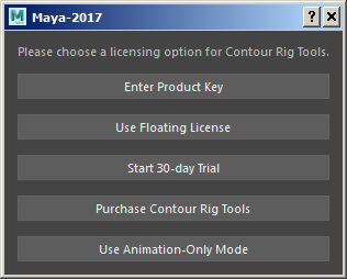
The Licensing Dialog
After installing Rig Tools and loading the plug-in the Licensing Dialog will be displayed. The Licensing Dialog can also be invoked later from the “Contour Rig Tools > About and Licensing” menu.
Internet Connectivity and Rig Tools Licensing
Rig Tools’ different licensing modes require different degrees of Internet connectivity, depending on whether they are node-locked licences or floating licenses.
Animation-only mode does not require Internet connectivity, either for activation or for ongoing use.
To start a Rig Tools trial the machine Rig Tools is installed on must be connected to the Internet. During the trial period Rig Tools periodically checks its license status against our license servers. After four hours of failing to reach the license servers the trial will be deactivated. Once Internet connectivity has been restored the trial may be reactivated from the Licensing Dialog, found in the “Contour Rig Tools > About and Licensing” menu.
To be used in fully-licensed mode, node-locked licenses require Internet connectivity for activation of the license, and require intermittent Internet connectivity during use, as Rig Tools periodically checks its license status against our license servers. There is a grace period within which Rig Tools will continue to function in fully-licensed mode if it cannot contact the license servers. This grace period is currently seven (7) days.
To be used in fully-licensed mode using a floating license server, either the floating license server must have Internet connectivity or it must use a proxy that has Internet connectivity.
Using Animation-Only Mode
To use Rig Tools in animation-only mode press the “Use Animation-Only Mode” button in the Licensing Dialog, found in the “Contour Rig Tools > About and Licensing” menu. Animation-only mode allows animating with rigs made in Rig Tools, but does not allow creating or modifying rigs, though it does allow adding Bone CVs to existing rigs.
Activating a Contour Rig Tools Trial
To begin a 30-day trial of Rig Tools press the “Start 30-day Trial” button in the Licensing Dialog. The trial allows use of all features of the fully-licensed mode. When the trial ends, or if Rig Tools is not able to periodically contact the license server, Rig Tools will revert to animation-only mode. If a trial is disabled because of a lack of Internet connectivity, it can be re-enabled through the Licensing Dialog.
Using a Node-Locked License
To use Rig Tools with a node-locked license press the “Enter Product Key” button in the Licensing Dialog, found in the “Contour Rig Tools > About and Licensing” menu, enter your product key in the dialog that appears, and press the “OK” button.
To move a node-locked license from one machine to another it must be deactivated on one machine and then activated on the other. To deactivate a license select the “Deactivate Product Key…” option from the “Contour Rig Tools > About and Licensing” menu. The machine a license is activated on must have Internet connectivity to deactivate the license. If you need to deactivate a license for a machine that does not have Internet access please contact us at support@notionalpipe.com and we can deactivate the license for you.
Using a Floating License
To use a floating license, you must have a floating license server configured and running, and must have network connectivity to it. For information on and assistance with setting up a floating license server please contact us at support@notionalpipe.com.
To obtain a lease to a floating license, press the “Use Floating License” button in the Licensing Dialog, which can be invoked from the “Contour Rig Tools > About and Licensing” menu. Enter the hostname or IP address and the port of your floating license server in the dialog that appears, and press the “OK” button. This will check out a lease to a floating license on your machine, if at least one license is available in your floating license pool. If no license is available an error dialog reading “Could not obtain lease because all floating licenses are currently in use.”
To stop using a lease and return the license to the license server’s pool, either exit Maya cleanly, unload the Rig Tools plugin, or select the “Stop Using Current License Server” option from the “Contour Rig Tools > About and Licensing” menu. If you stop using a lease by exiting Maya, or by unloading the Rig Tools plugin, Rig Tools will attempt to re-obtain a lease from the floating license server you have configured the next time Maya is started or the Rig Tools plugin is reloaded.
If Maya exits uncleanly, for instance because it crashes, or the computer it is running on is suddenly powered down, the lease will remain checked out for a period of time specified by the configuration of the floating license server. We recommend setting this value to something small.
Getting Started with a Simple Contour Rig
This tutorial will walk you through creating a simple Contour Rig Tools biped rig step-by-step. We’ll cover each Rig Tools feature in more depth later in the manual, but this should give you a taste of how easy it is to create flexible, high-performance character rigs with Rig Tools.
Putting down joints and bones
Start by loading up your character’s mesh and use the Contour Joint Tool to begin drawing joints. You enter this tool by selecting the Rig Tools ► Bones ► Contour Joint Tool menu item.
The Contour Joint Tool works a little bit like Maya’s Create Joint tool, but it creates Contour Joints instead of Maya joints, and has some additional functionality, allowing adjustment and insertion of joints while the tool is active.
To start laying down your character’s spine, hold control and click in the viewport to create a new Rig Tools joint chain right at the groin. Continue Control-clicking to add three more joints to the chain, one at the hips, one at the heart, and one at the base of the neck, as pictured. You can edit any of the joints at any time while drawing the chain by selecting the joint and moving it. After doing so, you can select the joint at the end of the chain and continue Control-clicking to add additional joints.
It’s often helpful to use Maya’s snap-to-mesh-center option when placing joints. Note that when the joint is created it will not snap to the center of the mesh, but moving it even a small amount will make it snap. Figure 1.
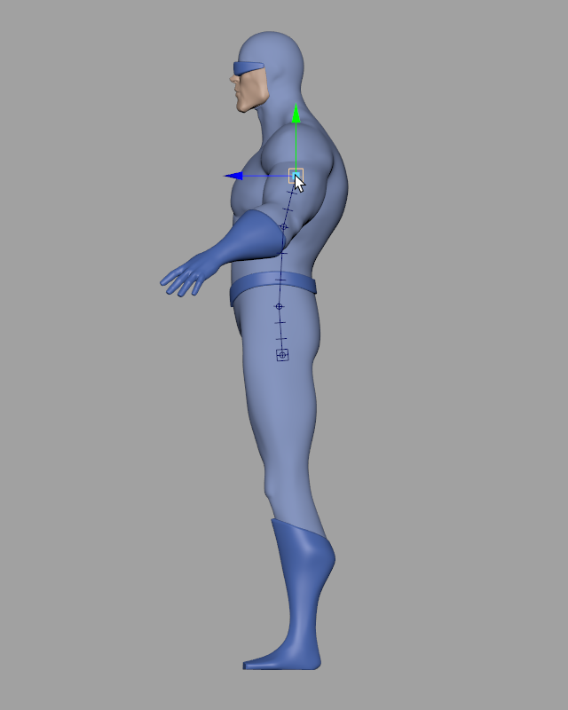
Figure 1
This arrangement of joints uses only one bone for almost the full length of the character’s torso, between the second and third joint of the chain. With Rig Tools that’s all we’ll need, as Rig Tools influences are splines, and we will be able to add “Bone CVs” to bend the spine later.
To rig the arms, we need to start a new joint chain. The Contour Joint Tool will automatically add to a selected chain, so to make a new chain make sure nothing is selected and Control-click at the clavicle to create the base of the chain. Now add four more joints, at the shoulder, the elbow, the wrist, and part way into the palm. Figure 2.
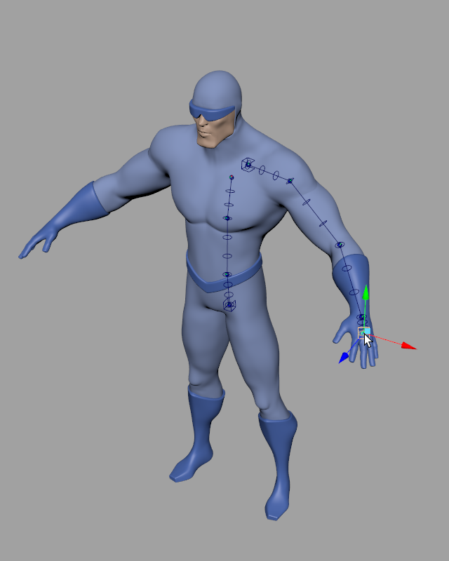
Figure 2
For the hips, we’ll place our joints a bit differently than we would for a standard Maya rig. A Contour Joint Chain controls deformation along its full length, and we want to be able to use the nice deformation that comes with that on the hip area itself. We will start our leg chain a bit above the hips, then place joints for the hips, knee, and ankle. This “overshoot” of the joint chain is something you will use frequently in Contour Chains to ensure good control over the shape of the chain through a joint and also the shape of the deformation where two chains overlap.
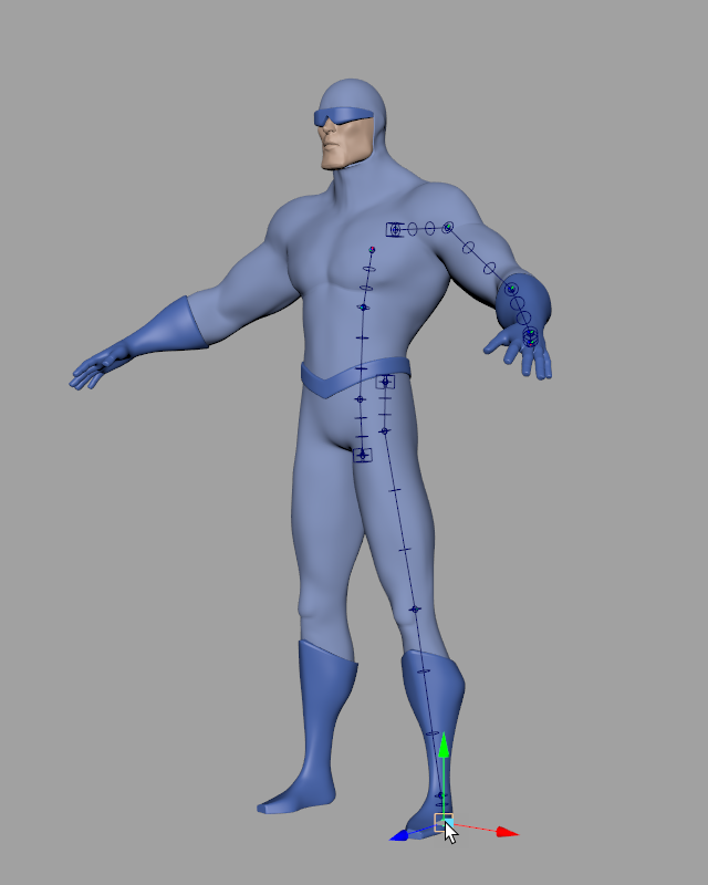
Figure 3
The ankle provides another example of this. While a Contour Joint Chain can bind to the mesh in almost any shape, when the underlying mesh has a sharp corner or 90 degree angle it’s best to use two different chains. For the ankle, we’ll add an additional joint to the leg chain, just below the foot, to ensure that the leg’s deformation continues straight through to the bottom of the foot. Then we’ll deselect the leg chain and start a new one—one joint at the ankle, one at the ball of the foot, and one at the tip of the toe.
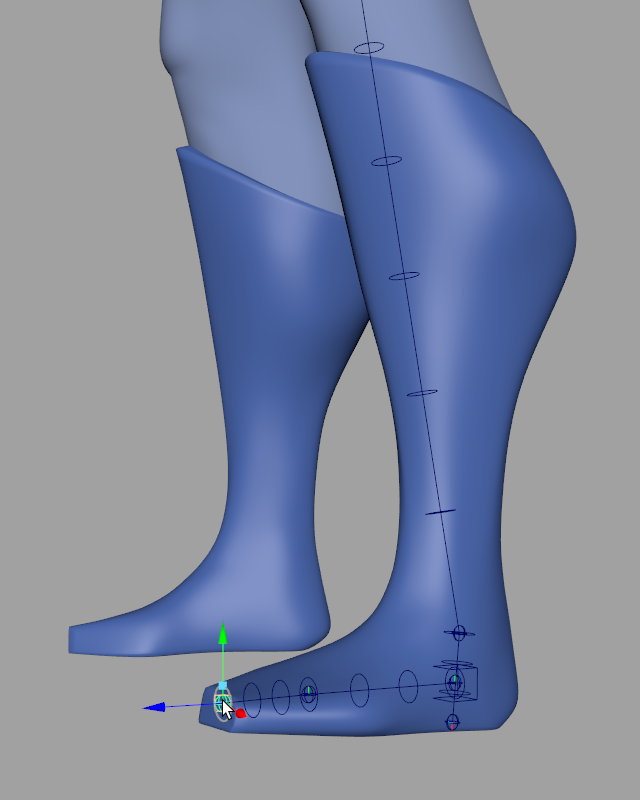
Figure 4
Let’s do a little organization. We can attach the arm to the torso by re-parenting it. Select the box at the base of the arm chain (it’s called a joint socket–—more on that later) and parent it to the chest joint. Figure 5. Do the same with the foot chain, parenting it to the last joint in the leg chain. Figure 6.
Don’t parent the hips yet though—–we’re going to do something different with them.
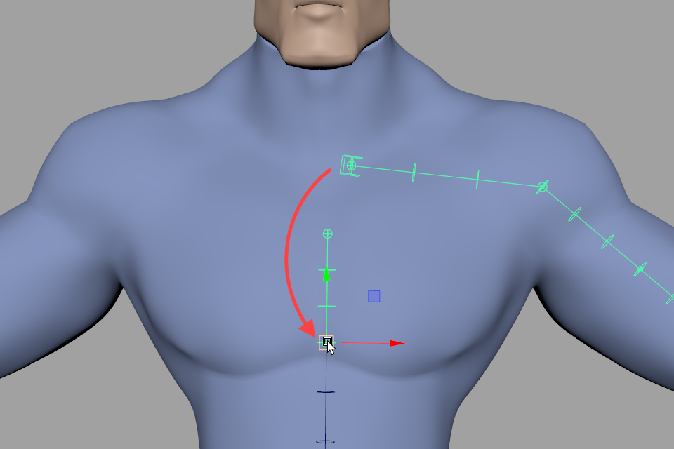
Figure 5
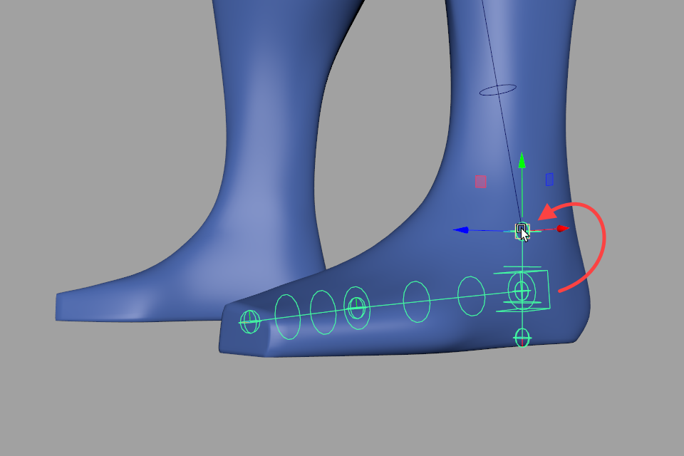
Figure 6
We can also re-name the nodes of a joint chain easily by selecting the chain’s joint socket and choosing Rig Tools ► Bones ► Rename Joint Chain from the menu. You’ll be prompted for a prefix, and after confirming the prefix all of the nodes in the chain will be re-named so that they begin with that prefix, and follow the standard namning convention for a Contour joint chain. Note that if you have already manually re-named any of the nodes in the chain, your changes will be lost. Figure 7.
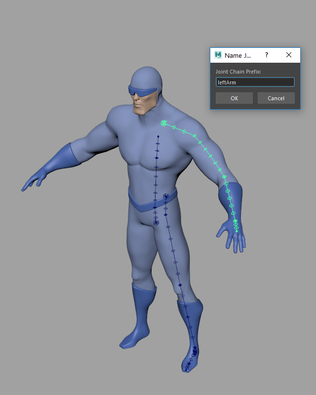
Figure 7
To mirror a Contour Joint Chain, select the socket(s) you want to mirror and choose Rig Tools ► Bones ► Mirror Joint Chain. Mirror the arm chain and the leg chain. The foot chain will automatically be mirrored, since it is parented to the leg chain. Figure 8.
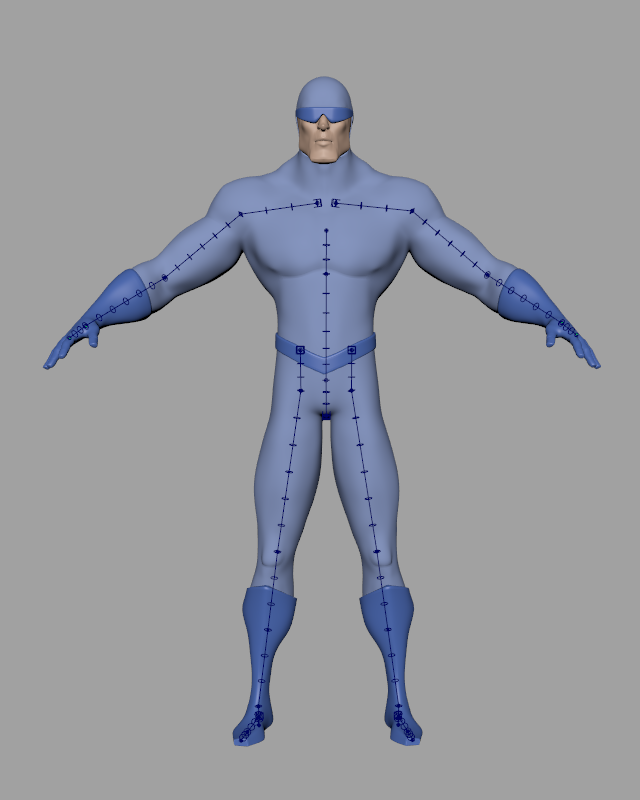
Figure 8
Once you’ve done that, we can attach the hips, but we’re not going to parent the socket as we did for the arms. The joint socket will need to be given different behavior from the hip joints, so instead we’re going to parent the hip joints themselves to the spine. Even though the nodes of a joint chain are created in a defualt hierarchy, onw that will often be desirable, they do not have to remain in any particular hierarchy. It’s perfectly OK to re-parent Contour Joints.
In this case we’ll want to group each joint before parenting, so that its rotation and translation remain zeroed out in its default position, and then parent it to the first spine joint. Figure 9.
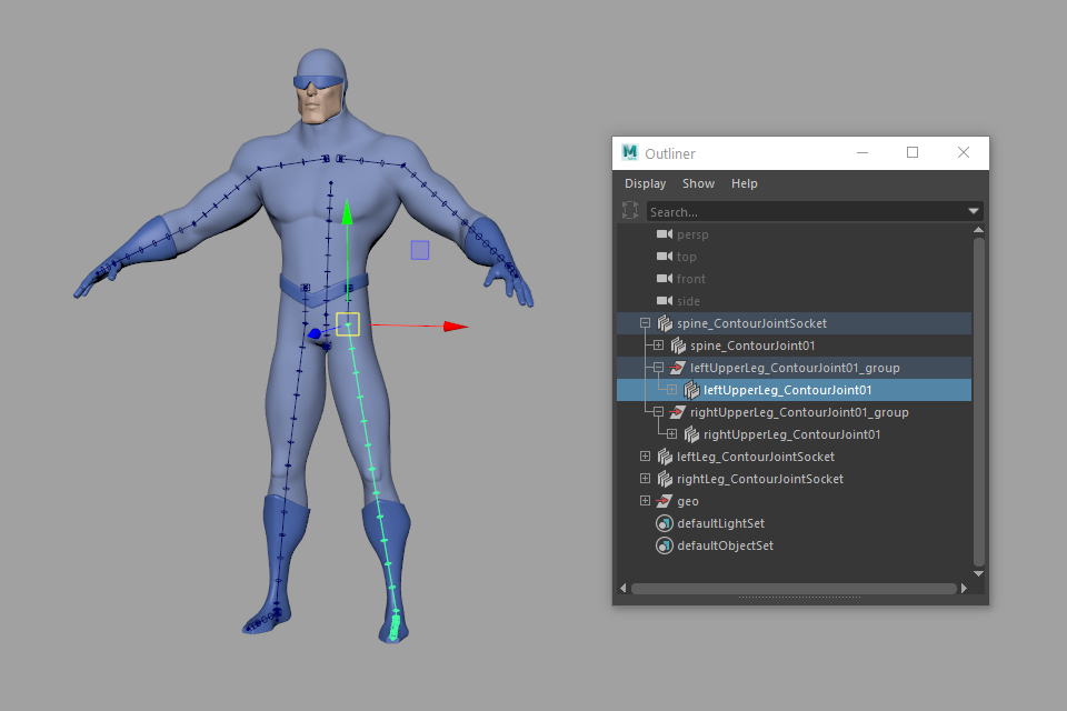
Figure 9
This will leave the sockets in world space, but that’s OK. We’ll be constraining them later.
Finally, we’ll add the head joint chain to complete the basic set of chains we’ll need for a bipedal character. We’ll be leaving out fingers for purposes of this tutorial. Figure 10.
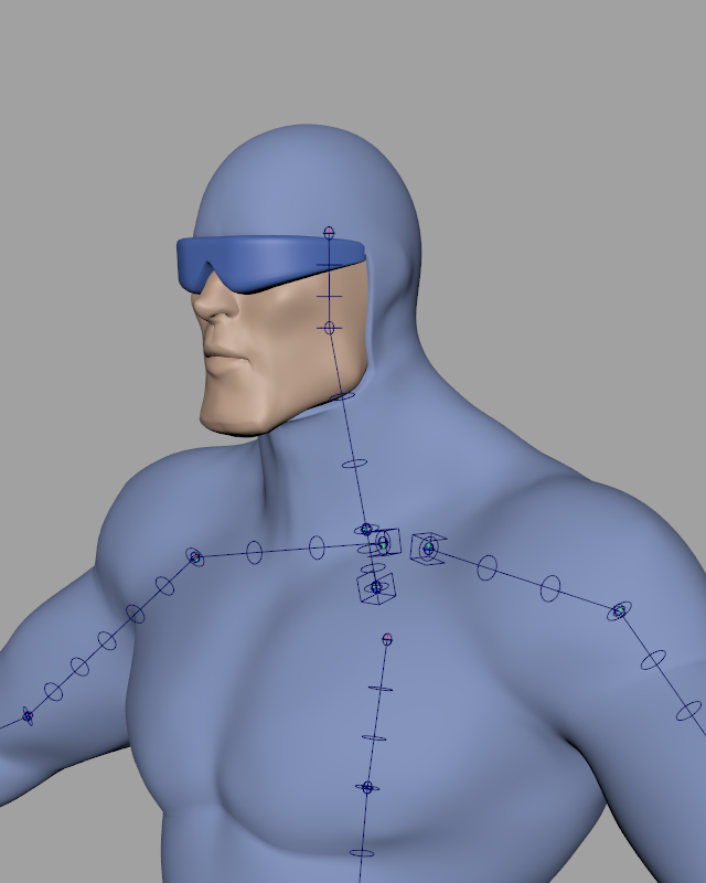
Figure 10
Binding The Mesh
Now the mesh needs to be bound to our joint chains. Unlike Maya joint chains, each Contour joint chain is a single influence. This means our character will only have eight influences at the start (a spine, a head, two arms, two legs, and two feet). This greatly simplifies things, but we need to do a little tweaking before we bind, to ensure that each of these influences deforms the character as nicely as possible.
You may have noticed some rings around the bones of our joint chain. These rings are a visual indicator of the radius of the joint chain. The radius affects how the Contour Deformer will deform the vertices of the mesh. For now we just need to set the radius of each joint chain to more or less the average radius of the geometry it deforms. Great precision is not necessary here—–most radius values that roughly fit the mesh will give good results.
To adjust a joint chain’s radius, select its joint socket and adjust the Radius attribute in the channel box until the indicator rings roughly match the geometry they’ll be deforming. Figure 11.
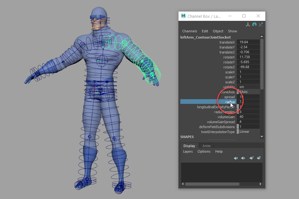
Figure 11
Once this looks right you can turn off visibility of the rings using Rig Tools ► Bones ► Disable Radius Indicator For All Bones, since the indicator rings can clutter your view of the scene.
Now things are ready for binding. To bind to the mesh, select all of the Contour Joint Sockets and the mesh geometry, and choose Rig Tools ► Deform ► Bind Mesh to Influences. You select the joint sockets, rather than the joints, because joint sockets are how you refer to an entire joint chain, and the joint chain (rather then any individual joint) is the influence we’re applying to our mesh. Note that you have to select all the joint sockets you want to bind, regardless of parenting—–you must select both the leg and foot sockets explicitly, for example.
Once bound, the deformation in the limbs should work very well already! You can adjust the softness of each joint’s deformation by adjusting its radius (which is different from the radius of the joint chain as a whole). Figure 12.
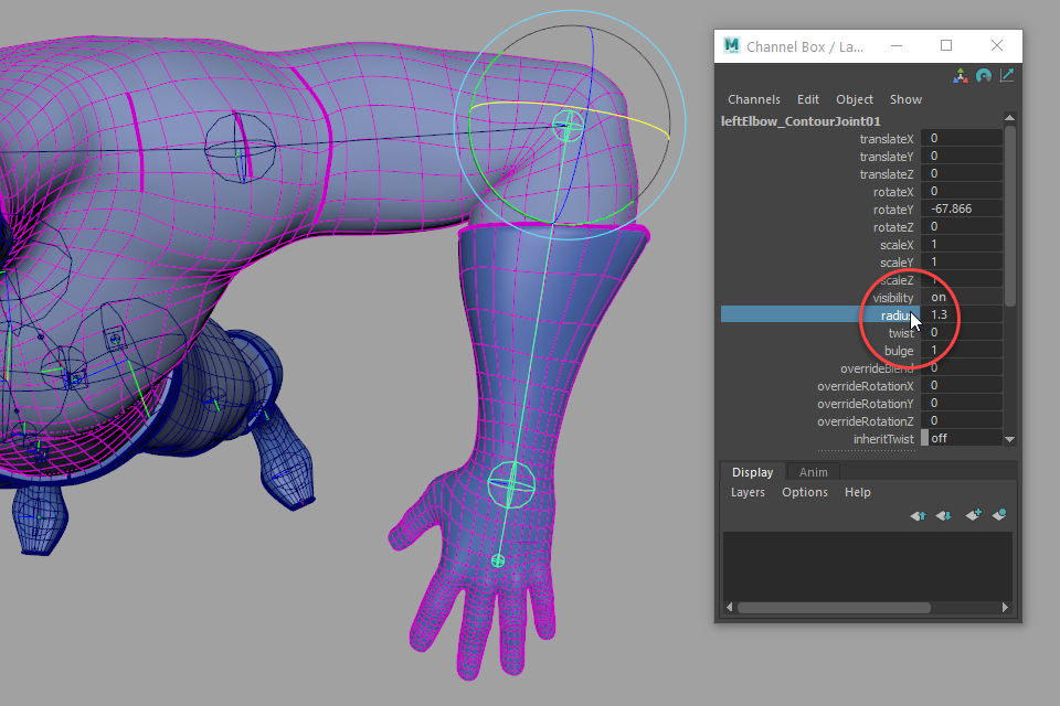
Figure 12
Where the joint chains overlap, however, we will have to paint some weights. Weight painting in Contour is much like normal Maya weight painting, but since there are far fewer influences there’s a lot less of it to do. Choose Rig Tools ► Deform ► Paint Weights and paint sensible transitions for the shoulders, hips, and ankles.
What a “sensible transition” is may be a little different from what you’re used to. In traditional Maya rigs, areas that will bend a lot in animation are normally where you would paint in transitions. In Contour rigs these areas are best left as much as possible to Contour’s automatic spline-based deformation. For instance, the deltoid area of the shoulder would be more or less solidly weighted to the arm chain, with the transition area in the trapezius and armpit areas. Figure 13.
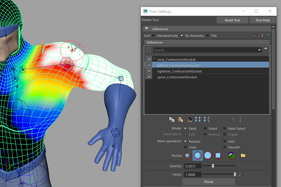
Figure 13
Contour deformation automatically propagates twist along joint chains to match the twist at each joint. Usually, this is exactly what you want, but in some cases you want to hold the twist in place. For instance, rotating the upper arm joint around the X axis will, by default, introduce twist in the shoulder area, which is likely to produce ugly deformation. Figure 14.
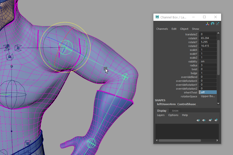
Figure 14
Turning on Inherit Twist for the shoulder or hip joint will tell it to maintain the twist of the previous joint in the chain, and produce perfect twist for a shoulder or hip joint. Figure 15.
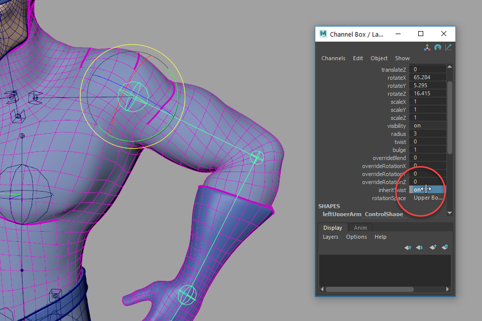
Figure 15
The next thing we need to address is deformation that weight painting alone can’t solve, in this case in the character’s head. Unlike the rest of the body, we don’t want spline deformation in the head, as this will distort the nose—–we want to deform the head rigidly. Figure 16.
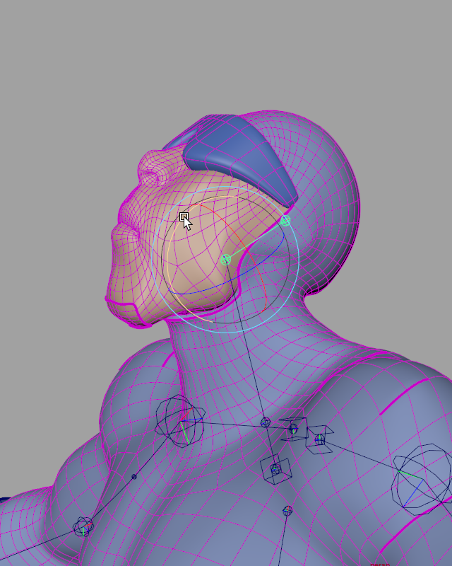
Figure 16
To fix this, you can add a rigid influence to the Contour Deformer. Rigid influences work just like standard Maya smooth skin influences, rather than Contour’s spline influences. You can add almost any transform as an influence. Let’s use a locator here. Parent the locator to the head joint, select it and the character mesh, and choose Rig Tools ► Deform ► Add Influence. Now paint weights for the head influence to appropriately cover the head areas you want to remain rigid. Figure 17.
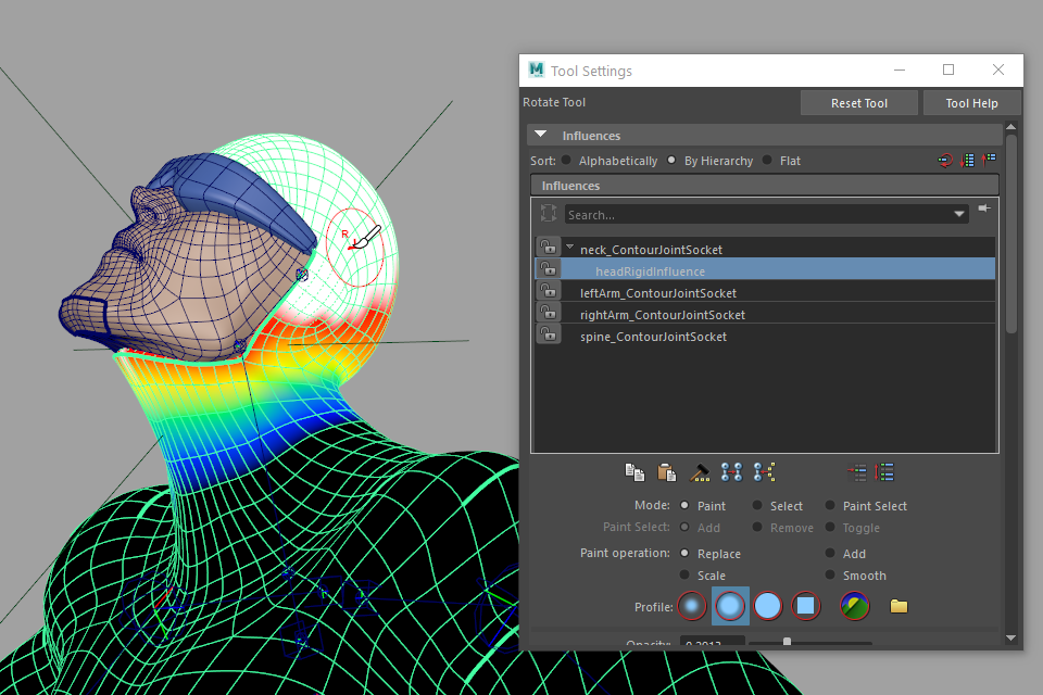
Figure 17
As you work you can mirror weights using the Rig Tools ► Deform ► Mirror Weights menu item. Remember to return the character to its default pose before mirroring, just as you would with Maya’s mirror weights tool. Since each Rig Tools Joint is “zeroed out” in its default position, you can do this by simply setting the translation and rotation values of every joint to 0.
You can also adjust the position of the influences non-destructively at any time. Simply choose Rig Tools ► Deform ► Rebind Mode ► Enter Rebind Mode. The mesh will turn dark red, snapping to its original shape, and any Contour transforms can be re-positioned.
In most cases, you should use the Contour Joint Tool to re-position Contour Joints. One of the functions of a Contour Bone is that it “buffers” a Contour Joint, meaning that the joint’s transformation values start at zero wherever it was placed with the draw joint tool. Using the Maya tools to move a joint will re-position it, but it will also drag or rotate the joint away from its buffer, causing non-zero transform values in the rest pose. Using the Contour Joint Tool to move a joint will change the orientation of the previous joint in the chain and the bone’s length instead, keeping the bone chain aligned in its rest position, with all Contour Joints properly buffered. There are some circumstances in which you may want to parent a Contour Joint to something other then a Contour Bone (we have just done so for the hips, for instance) but in general we recommend keeping the chain intact, as being able to return the character to its rest pose by zeroing out translate and rotate values is often useful.
When you’re satisfied with your changes, choose Rig Tools ► Deform ► Rebind Mode ► Leave Rebind Mode.
Control Rigging
Now it’s time to add some controls to the rig.
The first step is to give the spine the ability to bend. We used just one bone for almost the entire length of the spine, because Contour Bones are flexible. We can add Contour Bone CVs to our bones to give us control over the shape of the spline between two Contour Joints. To add a bone CV, select the joint at the base of the spine and choose Rig Tools ► Bones ► Add Bone CV. A new bone CV will appear at the halfway point of the bone. You can add as many bone CVs as you want, but in this case one will be sufficient to create nice clean arcs between the joints of the spine. Figure 18.
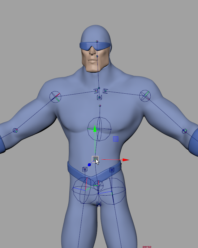
Figure 18
Now that the spine has a bone CV, there is a small issue. Translating the top joint of the spine leaves the bone CV in place, which isn’t what we want. Figure 19.
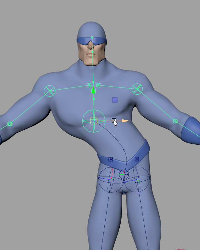
Figure 19
To create “spline IK”-like behavior for our spine, we’ll need to create an aim handle. Create Rig Tools Aim Handles is an all-in-one command that creates a target, constrains the rotation of the appropriate parts of the joint chain, and sets up the bone so that it will adjust its length to match its target. Select the top torso joint and choose Rig Tools ► Tools ► Create Rig Tools Aim Handles. A locator will be created, which can be used directly or parented under a control curve.
The aim target will make the spine rotate from the bottom, but it won’t control the rotation of the joint at the top of the spine. For that we’ll select our aim handle and the joint at the top of the spine, and choose Rig Tools ► Tools ► Create Rig Tools Orient. Now the handle will fully drive the top of the spine. Figure 20.
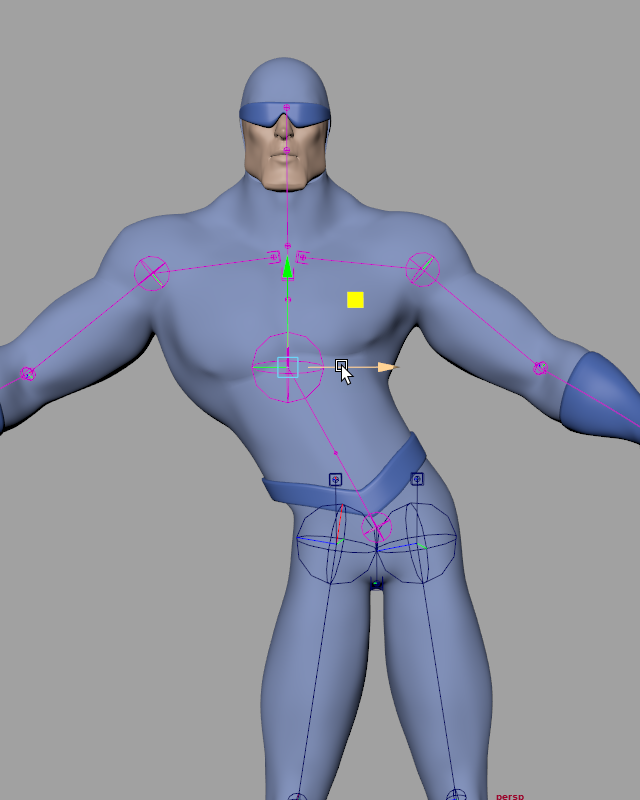
Figure 20
When we placed the joint chain for the legs, we talked a little bit about overshoot. Overshoot creates nice deformation here, but leaves us with an extra joint hovering above the hip. When we move the spine bone CV, the leg joints in the middle of the torso won’t follow along with it, making odd lumpy love handles show up in some positions. Figure 21.
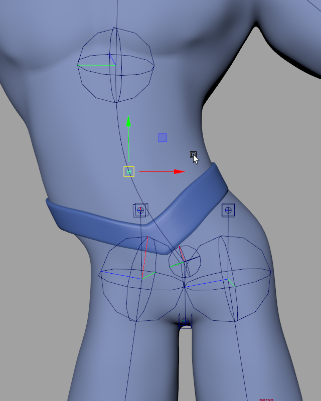
Figure 21
We’d like the extra joint to follow the same arc that the mesh is following. We can do this with a Contour Deform Field Constraint. Deform field constraints “constrain” the position and rotation of a transform using the same deform field that is deforming the mesh. Deform field constraints have a wide range of uses, but for now we’ll just use one to solve our hip issues. Select the joint socket at the base of the spine and the leg’s joint socket, and choose Rig Tools ► Tools ► Create Contour Constraint. Figure 22.
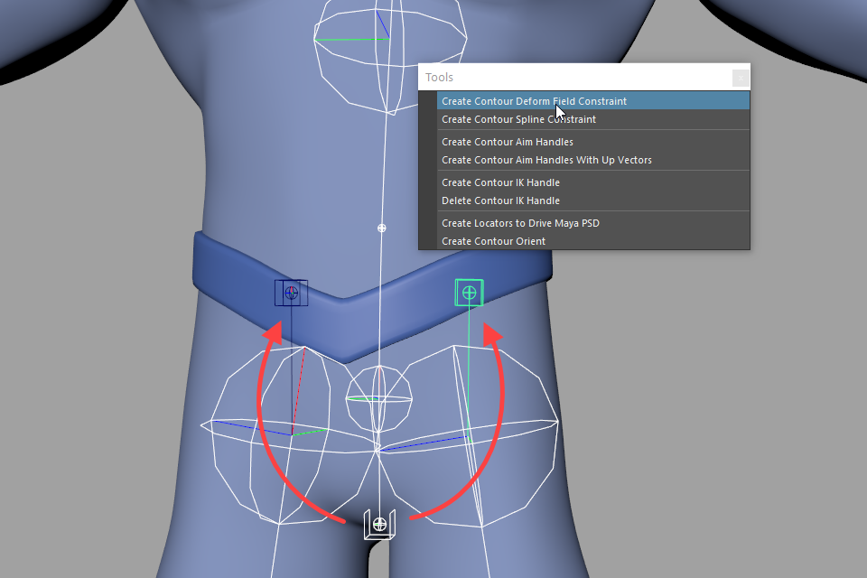
Figure 22
Now the hip joint is driven by the Contour spline and will behave nicely. Figure 23.
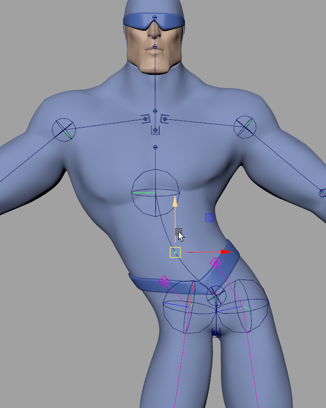
Figure 23
Because the joint chain begins within the body, and its first joint follows along with the deformation of the spine, we’ll get the same high quality deformation at the hip joint that we’ve seen in other areas of the body such as the elbow and shoulder. As with the shoulder, we’ll get the best results by weighting the most bendable areas very closely to the leg chain, and using weights to control how the effects of both leg chains blend at the crotch. Figure 24.
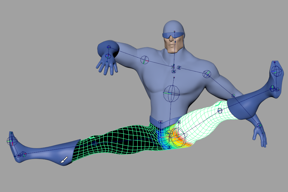
Figure 24
Contour comes with its own IK handle. Let’s add IK handles to the arms and legs. To add an IK handle, select three Contour Joints in the same chain in order, and choose Rig Tools ► Tools ► Create Contour IK Handle. A new IK handle and pole vector will be created.
The IK handle behaves much like a Maya IK handle, but it automatically controls the orient of the target joint, and has built-in stretchy behavior. The IK handle’s pole vector can be parented under the handle or controlled separately, as desired. Figure 25.
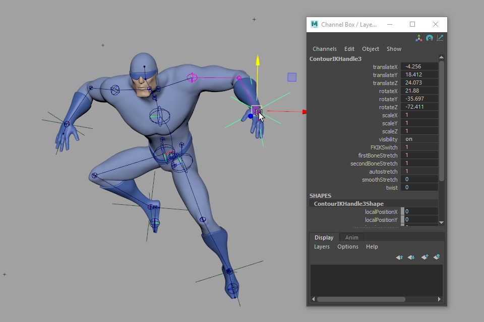
Figure 25
Contour’s aim and IK handles hook into the rotation and length override attributes on Contour Joints and Bones. This makes it very easy to blend back to FK when needed without adding additional rigging. You can, for instance, blend from IK to FK using the “blend” attribute present on the IK handles. The FK controls are simply the joints themselves—–no extra hierarchies needed! Figure 26.
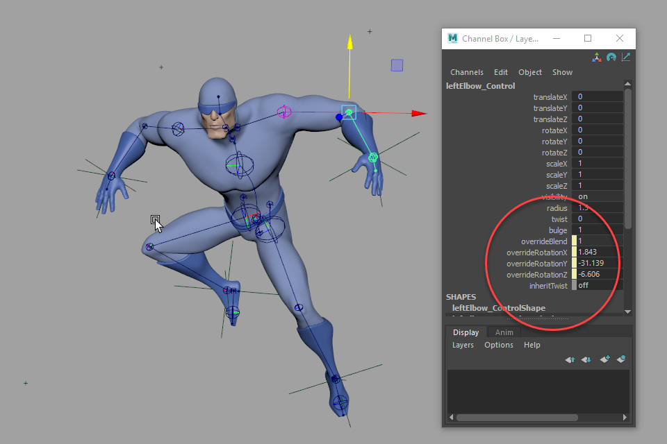
Figure 26
The arms and legs could use some extra control. We can add bone CVs to allow bending between the joints, just as we did for the spine. Figures 27 and 28.
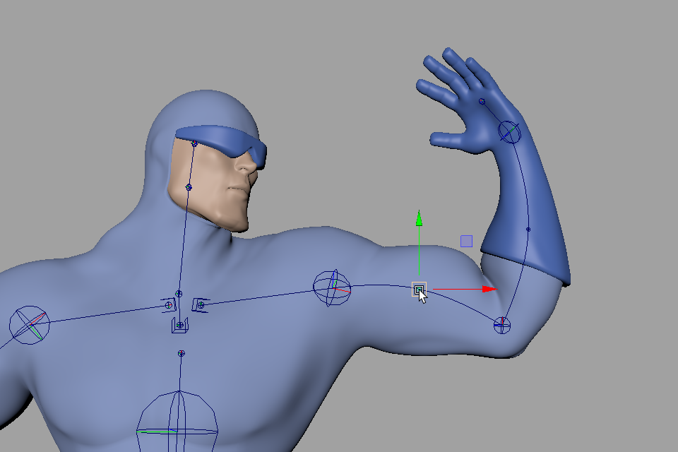
Figure 27
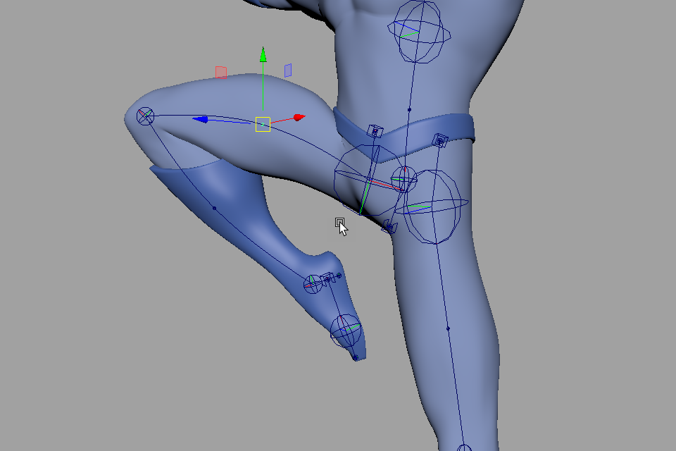
Figure 28
The final step in creating our rig is to add some control shapes. The Contour Joints and handles can be animated directly, but adding a few NURBS curves lets you customize the size and shape of your selection handles, and gives you the option of removing the Contour shape nodes. The simplest way to do this is select a handle or joint and use the Rig Tools ► Bones ► Add Circle Shape menu item. This creates a new shape under a handle or joint, and makes all the attributes of the handle or joint available when the control is selected. You can edit these shapes by adjusting their control points, as you would with any other NURBS curve.
Once we’ve added a shape to every handle, joint, or bone CV we intend the animator to use as a control, we can remove the Contour shape nodes for a cleaner-looking rig using Rig Tools ► Tools ► Delete All Contour Shape Nodes. This also improves the rig’s performance, as Contour shape nodes can slow down Viewport 2.0 drawing. But don’t worry—if we need to modify the rig we can always bring them back using Rig Tools ► Tools ► Restore All Contour Shape Nodes. Figure 29.
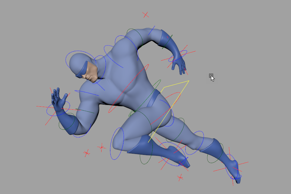
Figure 29
That’s it—–we now have a complete, usable rig! And though we didn’t do anything beyond the basics—–adding joints, painting some simple weights, and adding some aim/IK handles—–our rig has features you’d normally only see in complex, feature-level rigs built using an advanced auto-rigging system with a lot of effort put into deformation. Adding additional features like foot-roll and space-switching is beyond the scope of this tutorial, but it’s relatively easy to build them onto such a simple, flexible base. With Rig Tools, building rigs by hand becomes a possibility again, and auto-rigging can be radically simplified.
Joints and Bones
Introduction to Rig Tools Joint Chains
To drive its splines and deformers, Contour Rig Tools provides its own joints and bones. Contour Joints are similar to Maya joints, in that they’re transforms that can be animated directly or driven by other parts of a rig. They even look a bit like Maya’s joints. Figure 1.
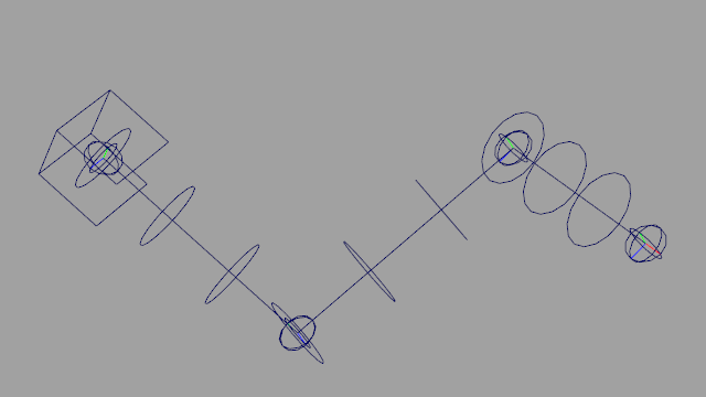
Figure 1
However, Contour Joints differ from Maya joints in fundamental ways, and offer functionality Maya joints don’t. We designed Contour so that, while it is possible to create a separate control structure and hide the joints from the animator, as is common in Maya rigs, it isn’t necessary to do so. Contour Joints are properly buffered for animation by default (ie. they can be zeroed out in every respect, including translation, without collapsing). Built-in rotation override makes it possible to rig them with optional inputs from a control rig—such as an IK handle—but still use the joints themselves for FK manipulation. And Rig Tools joint chains control Rig Tools splines in a way that offers clear visual feedback to the user.
To make this possible, a Rig Tools joint chain alternates between joints and bones, and its bones are actual nodes in the scenegraph that affect the behavior of the chain. Contour Bones act as a buffer for Contour Joints, and supply a concept of length that Maya’s joint chains lack. This length can be overridden and driven by a control rig just like joint rotation.
Joint Sockets and Chains
Every Rig Tools joint chain begins with a “Joint Socket,” which carries attributes that relate to the chain as a whole. These include settings that apply to the joints and bones within the chain, but also to the spline and deform field that the chain drives, such as the radius and density of the deform field. Figure 2.
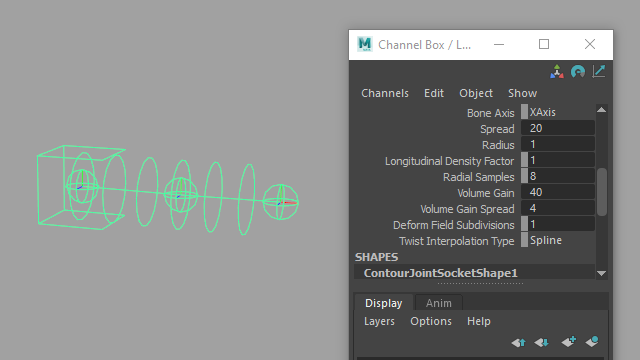
Figure 2
Under normal circumstances, a joint chain will drive a single spline and an associated deform field, and their behavior will be controlled by attributes on the joint socket. Figure 3.
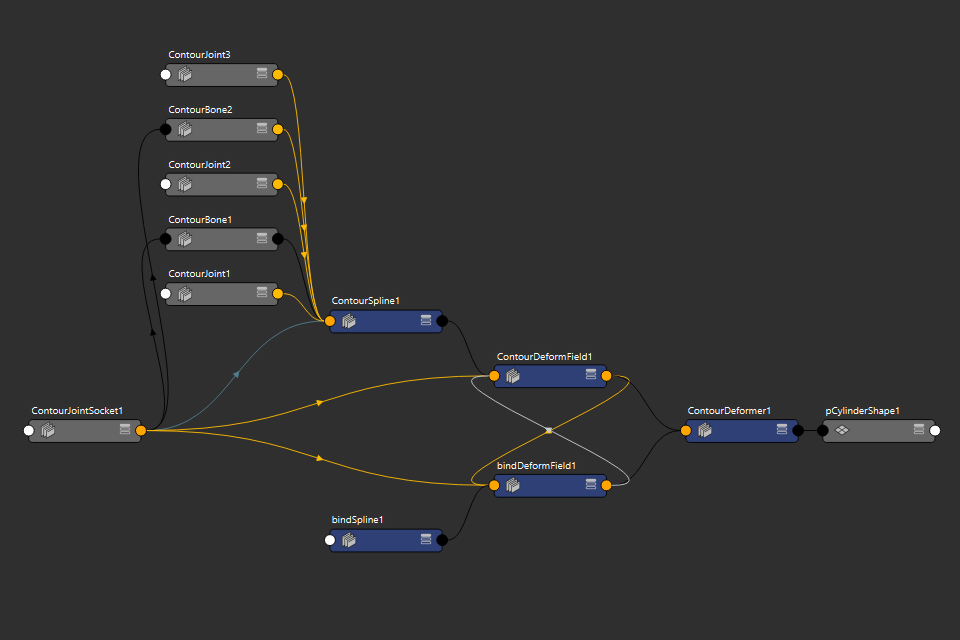
Figure 3
Joint sockets are also used by our tools any time you need to refer to a joint chain by selection, or in a call to our Python API. For instance, to create a deform field constraint for a joint chain you select the chain’s joint socket followed by the node you want to constrain.
Having a node you can always use to refer to a specific joint chain and its spline and deform field is important because Rig Tools joint chains are extremely flexible. Once a joint chain is created, it does not need to maintain its original hierarchy to remain a chain. You can insert transforms into the joint chain hierarchy, or parent joints or CVs to other hierarchies. In fact, a joint socket can become “childless,” without any joints or bones parented to it, and the chain will continur to work. The chain’s joint socket will still be used to refer to it, and to its spline.
Separate Joints and Bones
In addition to a joint socket, Rig Tools joint chains include both joints and bones. A Maya joint hierarchy is a simple list of joints: Figure 4.
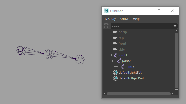
Figure 4
A Rig Tools joint chain, however, alternates between joints and bones: Figure 5.
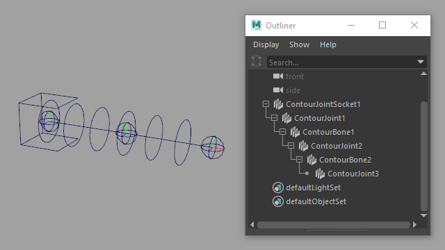
Figure 5
Rig Tools bones can’t be translated or rotated directly. Their purpose is to provide attributes relevant to the next joint in the chain. Figure 6.
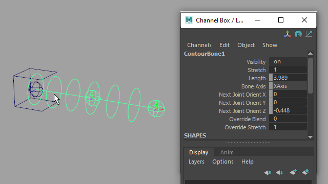
Figure 6
Every bone has a length, and that length defines how far from the previous joint the next joint in the chain will be positioned. Figure 7.
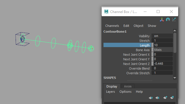
Figure 7
Each bone also has a “Next Joint Orient” attribute, which is similar to the “Joint Orient” attribute present on Maya joints, but affects the following joint in the chain. Figure 8.
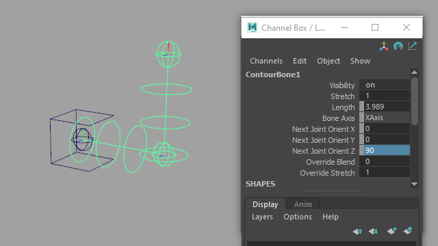
Figure 8
Between the Length and Next Joint Orient attributes, a bone completely buffers the joint that comes after it; a joint will return to its default position when its translate and rotate values are zero. Maya joints buffer their own rotation (through the Joint Orient attribute) but do not buffer translation at all; returning a Maya joint’s translate values to zero does not return it to its default position, but instead collapses the joint chain.
In addition to a Length attribute, Rig Tools bones have a Stretch attribute that multiplies the bone’s length. This makes it very easy to create rig behavior that stretches the bone, without losing information about its default length. Figure 9.
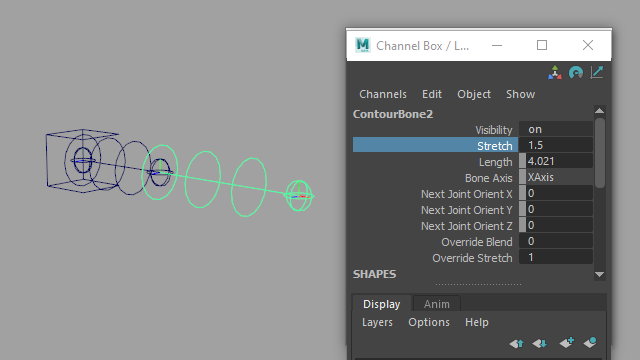
Figure 9
To define which axis the bone points down, each joint chain has a Bone Axis attribute, found on its joint socket. Figure 10.
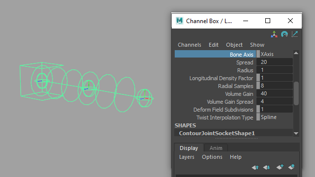
Figure 10
Rig Tools joint chains default to pointing down the X axis, as this is most appropriate for an XYZ rotation order. If using Y or Z as the bone axis, rotation order should be changed accordingly.
Rig Tools bones also support negative bone axes, which is important for properly mirroring transforms. We usually assume a positive bone axis on a character’s left side (e.g. +X) and a negative bone axis on its right (ie. -X), but this is only a convention and other arrangements are possible.
Joint Chain Radius
Rig Tools joint chains also have a radius, visually indicated by the rings surrounding the spline. The Radius attribute is found on the joint socket, as it applies to the entire joint chain. Figure 11.
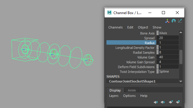
Figure 11
A chain’s radius is important information for the Rig Tools deformer, reflecting the approximate radius of the geometry being deformed. For instance, a wide pipe might require a different deformation than a skinny wire. The radius should be adjusted so that it is as close as possible to the average radius of the geometry deformed by the chain. If the geometry varies greatly in radius, err on the side of the largest radius. Figure 12.
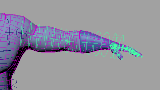
Figure 12
Once your joint chains’ radiuses have been adjusted the radius indicators are usually no longer needed. Its display can be toggled with Rig Tools ► Bones ► Disable Radius Indicator for All Bones and Rig Tools ► Bones ► Enable Radius Indicator for All Bones.
Using the Rig Tools Joint Tool
Like Maya, Rig Tools includes a tool for drawing joints. Unlike Maya, this tool can also be used to modify joint chains after they have been drawn, or while they are being drawn.
Starting a New Joint Chain and Adding Joints
To begin creating a new joint chain, choose Rig Tools ► Bones ► Rig Tools Joint Tool from the menu, and control-click in the view. A joint socket and joint will be created. Figure 13.
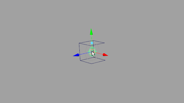
Figure 13
Clicking and dragging will reposition the joint, while control-clicking will add a new joint to the chain. New joints may be added to a chain at any time by selecting the last joint in the chain and control-clicking with the Rig Tools Joint Tool active. If a joint in the middle of the chain is selected, a new joint will be inserted between the selected joint and the next joint in the chain. Figure 14.
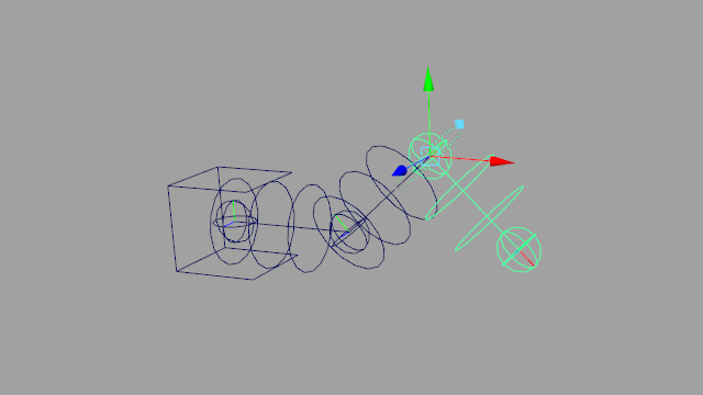
Figure 14
Repositioning Joints
While the Rig Tools Joint Tool is active, selecting any joint in the chain will allow you to reposition it. Using the Rig Tools Joint Tool to reposition joints actually modifies the Next Joint Orient and Length values of the bones in the chain, keeping the joint’s transforms zeroed out. Figure 15.
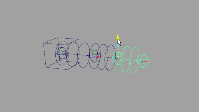
Figure 15
You can use any of Maya’s snapping modes when respositioning joints, including “Snap To Projected Center”. However, control-clicking to add new joints does not respect snapping modes. To make a newly created joint snap, simply reposition it immediately after placing it.
While a joint is selected and the Rig Tools Joint Tool is active, the selected joint will be surrounded by a circular manipulator that can be used to “roll” the joint. By repositioning and rolling joints visually you can fully define the orientation of any joint in a chain without leaving the tool. Figure 16.
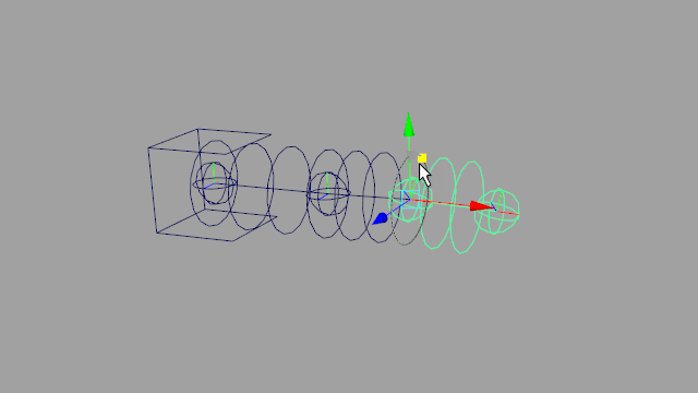
Figure 16
Modifying Joint Chains
Duplicating Joint Chains
Simply using Maya’s duplicate command on a Rig Tools joint chain won’t work properly—the specified bone and joint nodes will be duplicated, but they will not include the connections they need to function as a Rig Tools joint chain. Instead, joint chains must be duplicated using the Duplicate Joint Chain command.
To use this command, select one or more joint sockets and choose Rig Tools ► Bones ► Duplicate Joint Chain. All selected chains will be duplicated, along with any nodes parented to any joint or bone within that chain. If another joint chain is parented to a joint or bone in the chain, it will be duplicated as well.
Mirroring Joint Chains
Joint chains can be mirrored across the X, Y, or Z axes with Rig Tools ► Bones ► Mirror Joint Chain. Choose the mirror axis in the option box associated with the “Mirror Joint Chain” command.
Mirroring works just as duplication does—you can select any number of joint chains, and they and anything parented to their constituent joints and bones (including other Rig Tools joint chains) will be mirrored. Mirrored bones receive a negative bone axis so that the rotation of joints is correctly mirrored. Figure 17.
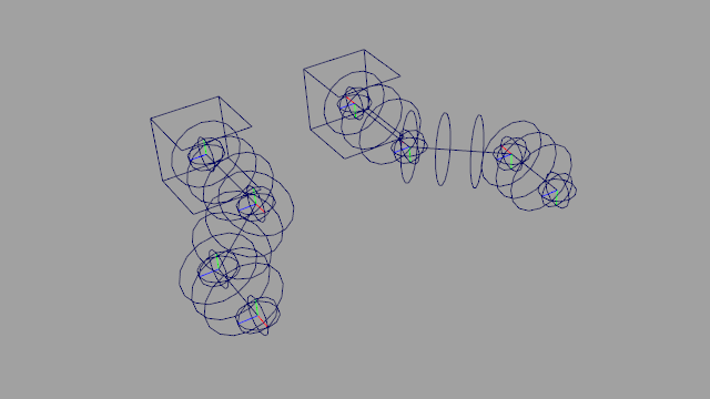
Figure 17
If using negatively scaled spaces for mirroring, the joint chain may instead be duplicated and then grouped under a negatively scaled space (for instance, one with scale values of -1,1,1.) This allows for true mirroring of both translation and rotation. Rig Tools has no problem with joint chains with non-uniform scale values, including negative values. Figure 18.
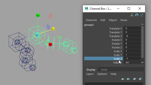
Figure 18
Adding and Deleting Joints and Bones
To add a joint to an existing chain, re-enter the Rig Tools Joint Tool and select any joint in the chain. Control-clicking will add a new joint immediately after the selected joint. Figure 19.
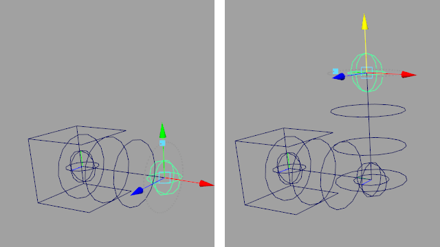
Figure 19
Alternatively, you can select any joint in a chain and use the Rig Tools ► Bones ► Add Joint And Bone to Chain command. A new joint will be added at the end of the chain if the selected joint is the last joint in the chain, or at the midpoint of the selected joint and the following joint if the selected joint is not the last joint in the chain. Figure 20.
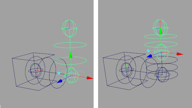
Figure 20
To delete a joint and its bone, you can enter the Rig Tools Joint Tool, select a joint, and press delete. You can also use the Rig Tools ► Bones ► Delete Joint And Bone from Chain command. Rig Tools will remove the joint and bone, and reorient the previous joint and bone to keep the chain pointing down the correct axis.
To remove an entire joint chain, select its joint socket and use the standard Maya Delete command.
Bone CVs
Unlike Maya bones, Rig Tools bones are not rigid. Since they ultimately control a spline that is used to deform the mesh, you can insert “Bone CVs” into a joint chain at any time. Bone CVs control the curvature of the spline between joints, and make bendy cartoon limbs, tentacles, ropes, and other tube-like objects very easy to rig. Figure 21.
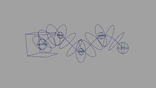
Figure 21
One big advantage of bone CVs is that they can be added at any time, even in a referenced rig. This means an animator can add CVs as needed on a per-shot basis without cluttering up the rig for other shots.
To add a bone CV to a bone, select a Rig Tools joint or Bone CV and choose Rig Tools ► Bones ► Add Bone CV. A new CV will be created, halfway between the selected node and the next joint or bone CV. You can add as many bone CVs as you want. Figure 22.
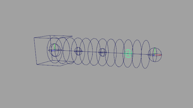
Figure 22
When you create a bone CV, it will have a “Bone CV Socket”. This socket buffers the bone CV, just as bones buffer joints, so that the CV will return to its default position when zeroed. When the bone is stretched, by changing its Stretch or Override Stretch attributes, the position of the bone CV socket along the bone axis will be scaled along with the bone. Figure 23.
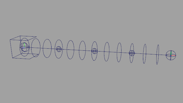
Figure 23
Bone CVs can be removed by choosing Rig Tools ► Bones ► Delete Bone CV from the menu.
Override Rotation and Stretch
Rigging often requires you to provide more than one way to control a joint—for instance, to allow for FK/IK switching. This is traditionally accomplished by creating a rig that blends between the effects of multiple control structures using constraints or math nodes.
Rig Tools joints and bones offer an alternative method that allows you to override joint rotation or bone stretch directly on the joint or bone, with built-in override and Override Blend attributes. Figure 24.
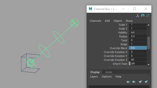
Figure 24
This reduces control rig complexity, and makes it viable to animate with the joints themselves as one control method. That’s how Rig Tools’ built-in IK handle works; the handle controls the joint’s rotation override, allowing you to animate the joint chain itself as FK controls when the IK handle is not active.
When not being used by an IK handle, the override can be linked to any attribute as needed. Internally, the joints use a quaternion slerp to perform the blend, equivalent to a blended orient constraint in “Shortest” mode. This makes it easy to link the values to a variety of inputs without worrying about gimbal issues when blending between the two.
There are some caveats when constraining to a joint with overridden rotation. See Constraining to a joint with rotation overrides.
Bone Display and Selectability
Because the joints and CVs are right on top of the bones, it’s easy to accidentally select a bone when trying to select a joint or CV. Rig Tools provides a menu option in the Rig Tools ► Bones menu to toggle all bones selectable or unselectable.
The bone radius indicators can also be visually confusing in a rig with lots of joint chains. Each bone shape node has a “Draw Joint Chain Radius” attribute that controls whether the radius indicators associated with that section of the spline are displayed. Figure 25.
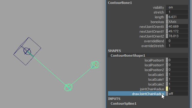
Figure 35
The Rig Tools ► Bones menu also provides commands to globally show or hide the radius indicators for existing joint chains. New chains will still be created with the radius enabled.
Splines and Deformation
Introduction to splines and deformation
The Rig Tools deformer is in some ways similar to Maya’s Smooth Skin deformer. Both have joints as inputs and influences that can be weight-painted. But in order to provide smooth and reliable spline deformation, Rig Tools does things a bit differently.
Rig Tools joints don’t directly input into the deformer like a Smooth Skin deformer. Instead, Rig Tools joints and bone CVs output to a Rig Tools spline. The Rig Tools spline runs through the joints and bone CVs of a joint chain and outputs a deform field. Each deform field then outputs to the Rig Tools deformer as an individual influence. Figure 1.
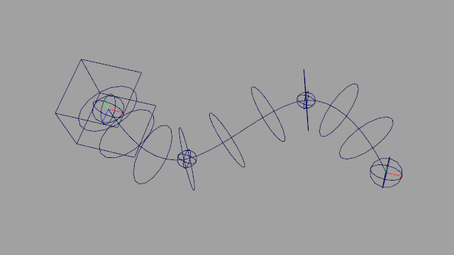
Figure 1
The deform field adjusts the positions of mesh vertices so that they “spread” along the length of the spline, providing excellent deformation in areas of high curvature, maintaining volume and creating fair curves in the silhouette of the mesh. It also reduces self-intersection and eliminates candy-wrappering, as long as the mesh is sufficiently dense to support the required twist. Figure 2.
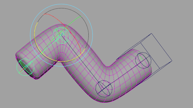
Figure 2
A rigid influence added to the deformer doesn’t have a Rig Tools spline and is treated as a simple transform, very similar to a standard smooth skin influence.
Binding meshes to a Rig Tools spline
To bind meshes to influences using the Contour deformer, select one or more influences and one or more meshes, and choose Rig Tools ► Deform ► Bind Mesh to Influences from the menu. Influences can be Contour joint sockets or non-Contour transforms, but cannot be Maya joints. The order of the selection doesn’t matter—each mesh will be bound to all influences.
A new deformer will be created for your meshes, with a Rig Tools spline influence for each joint socket and a rigid influence for each transform that is not a joint socket. Contour will only bind meshes that are actually selected, rather than binding meshes that are descendants of the selected nodes. Transforms that have more than one mesh shape cannot be bound.
The menu item Rig Tools ► Deform ► Bind Mesh to Influences and Descendant Contour Chains will not only bind a mesh to the selected influences, but will bind the mesh to any Contour joint chains that are descendants of those influences. This allows binding all of the joint chains of an entire character at once, if they’re in a single hierarchy.
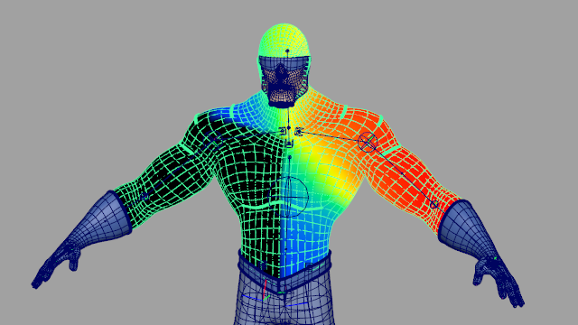
Figure 3
Once your mesh is bound to a Rig Tools deformer, you can add new joint chains or rigid influences with Rig Tools ► Deform ► Add Influences. If a transform that is not a joint socket is selected, the influence added will be a rigid influence. You can use this menu item to add meshes as rigid influences as well.
The deformation produced by the Rig Tools deformer generally looks good even immediately after binding. Test out the effect by moving some of the Rig Tools joints around. If the spline radius was set correctly when laying out the joint chains, areas like elbows and knees may need no further adjustment. Figure 4.
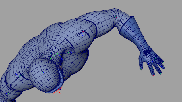
Figure 4
Unbinding Meshes
To unbind one or more meshes that have a Rig Tools deformer, select the meshes and then pick Rig Tools ► Deform ► Unbind Meshes. This will delete the Rig Tools deformer of the selected meshes.
Rebind Mode
In cases where adjustment is needed, Rig Tools makes it easy to rebind the mesh without losing any weight painting data. Rebind Mode is used to adjust the position of rig elements after the mesh has been bound. Rebind mode can be entered by choosing Rig Tools ► Deform ► Rebind Mode ► Enter Rebind Mode.
Once Rebind Mode has been entered, rig deformation is temporarily disabled. Rig elements can be adjusted now. The preferred way of adjusting Rig Tools joint chains is with the Rig Tools Joint Tool. Using this tool will allow joints to be moved without affecting their children, and will preserve the fully buffered status of the joints. Figure 5.
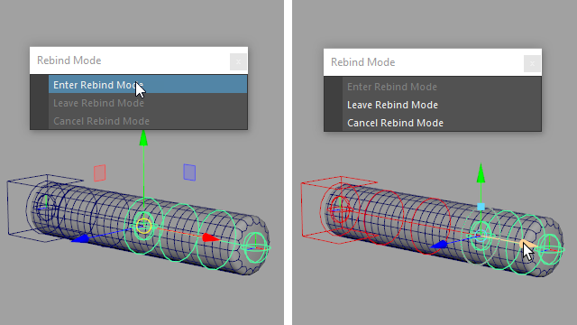
Figure 5
Rebind Mode is not a tool, it is a mode, so other tools can be used to manipulate rig elements as well. Bear in mind the potential effects on the final transform values however.
When satisfied with the position of the joints, exit Rebind Mode with Rig Tools ► Deform ► Rebind Mode ► Leave Rebind Mode. The deformation is rebound using the current position of rig elements as the default position, and all other bind information is restored. Figure 5b.
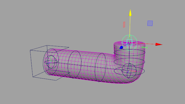
Figure 5b
If undesirable changes have been made to the rig, Rebind Mode can be exited without changing bind information. Rig Tools ► Deform ► Rebind Mode ► Cancel Rebind Mode will re-apply the bind information that was present when Rebind Mode was entered. Note: If the rig is not in the same position, this will cause the mesh to snap to the new pose.
Deformer Settings
The Rig Tools deformer provides great deformation right from bind, but it can be necessary to tweak settings to optimize appearance and performance. The attributes that affect deformeration are found in two places: attributes that affect only a single joint or bone CV are found on the joints and CVs themselves, while attributes that affect the entire Rig Tools spline are found on the joint socket.
Joint Radius
A joint’s Radius attribute controls the sharpness of the curvature of the spline as it nears that joint. A small radius will cause a sharp bend. As the radius is increased the joint will form a smoother, gentler bend. The radius can be increased until it includes adjacent joints or bone CVs; increasing it further has limited effect. Note that the Radius attribute found on joints is different from the Radius attribute found on Splines, which controls the distance from the spline at which the deformer produces the most pleasing deformation. Figure 6.
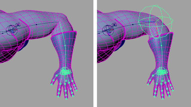
Figure 6
Twist and Inherit Twist
The Contour deformer calculates twist using Rotation Minimizing Frames, giving stable twist up to 180 degrees for the twist produced from the rotation of joints and the shape of the spline.
Each joint and bone CV has a Twist atrribute that can be used to directly control twist at its location along the spline. This twist is layered on top of twist produced by joint rotation, and is stable for arbitrarily large values of twist, including those above 180 degrees, as long as the mesh is dense enough to avoid candy-wrappering. Figure 7.
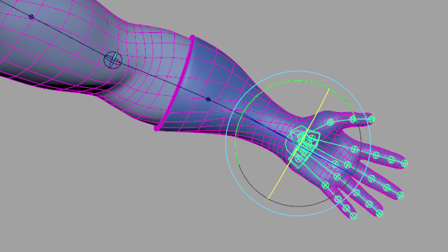
Figure 7
The Inherit Twist attribute found on joints controls where the twisting occurs when a joint is rotated. When a joint’s Inherit Twist attribute is set to true, the joint uses the rotation of the previous joint in the chain instead of its own rotation to calculate twist. This locks twist for things like shoulders, so that the twist occurs between the shoulder and elbow instead of in the shoulder itself. Figure 8
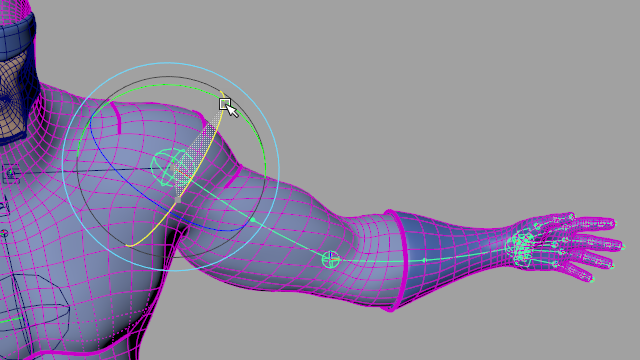
Figure 8
Bulge
Each joint and bone CV has a Bulge attribute that can be used to grow or shrink the mesh around the spline as it nears the joint or CV. Figure 9.
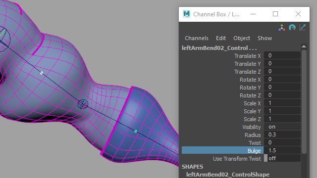
Figure 9
Spline-Wide Deformation Settings
Rig Tools provides high-level settings that adjust how an entire spline deforms a mesh. These attributes are found on the corresponding joint socket.
Spread: At sharp corners, naive spline-based deformers like wire deformers will have interpenetration or overlapping geometry. The Rig Tools deformer tries to avoid this by “pushing” the geometry out in the neighborhood of areas of high curvature. The Spread atytribute controls the strength of this effect. Too much spread can make the deformation imprecise and wiggly, while too little will cause stiff deformation that just follows the spline.
Values between 10 and 30 are usually the most useful. Very high values will produce increasingly smaller effect, but may incuir a substantial performace penalty. Figure 10.
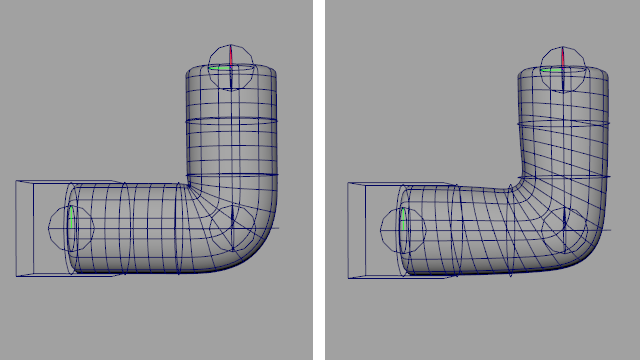
Figure 10
Radius: The Radius attribute—found on joint sockets, not joints—of the spline is the distance from the spline at which the deform field will produce the most pleasing results. Areas inside and outside of the radius will still be deformed, but results may become increasingly less appealing as geometry moves further from or closer to the spline. Small values, relative to the rough diamter of the mesh, will produce results that are similar to a wire deformer, while values that are too large will cause the deformation to become “faceted” on the outside of bends, and too smooth on the inside. Figure 11.
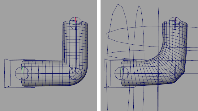
Figure 11
Longitudinal Density Factor: For performance reasons, Rig Tools uses a sampling method to approximate an ideal mathematical model of deformation. The Longitudinal Density Factor constrols density of the samples taken down the length of the spline. When deforming meshes that stretch but do not bend much, this value can be decreased to optimize performance. Alternatively, when geometry density is very high and curvature very large, it may be necessary to increase this value for greater accuracy at a cost to performance. LDF’s default value of 1 is a good balance for most cases, and this value can usually be left at the default.
The Spread attribute relies on the LDF to calculate how far to push geometry. Changing the LDF will likely also require a readjustment of the Spread value to achieve the same results.
Radial samples: The radial version of the LDF, this controls the density of the field around the spline. This value can be increased to improve accuracy for high density meshes. In particular, very rapid rotation of a mesh around a spline can cause instability in the results of deformation when this value is at the default, and increasing it will sove this.
Radial samples is set to 8 by default. Lowering the samples below 8 is possible but not recommended. Increasing the samples above 8 will improve accuracy but at a high performance cost. Like the LDF, the default value is usually correct.
Volume Gain: Volume Gain controls how much the inner surface of the mesh at a sharp bend in the spline smooths itself out to avoid “pocketing” and volume loss. Volume Gain pushes vertices away from the spline in the neighborhood of an acute bendin the spline, while Spread moves geometry along the spline.
The Volume Gain attribute controls the strength of this effect. Usually values between 20 and 60 produce the best results. The default value of 40 produces good results for most geometry. Figure 12.
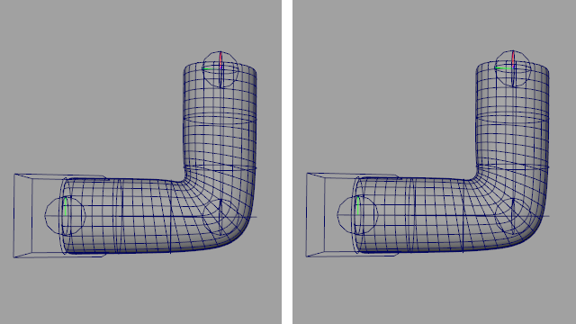
Figure 12
Volume Gain Spread: This attribute controls how wide an area up and down the spline the effect of Volume Gain covers. Larger values will result in more volume and softer inside corners. Figure 13.
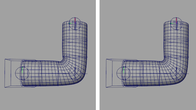
Figure 13
Twist interpolation Type: Sets the method used to interpolate twist along the spline. Spline interpolation eases in and out of the joints, concentrating more of the twist in the middle of the bone. Linear distributes the twist evenly. Some meshes benefit from a more even twist. Figure 14.
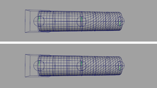
Figure 14
Influences and Weights
Using rigid influences
The Rig Tools deformer provides the most value in areas where the desired deformation is smooth and soft, such as arms, legs, spines and tails. However, there are some areas where the distribution of bending and spreading Rig Tools provides is undesirable. In these areas, adding rigid influences to your deformer gives you explicit control over how an area will deform. The rigid influence works exactly like a standard smooth skin influence, and can be adjusted with painting or the Rig Tools Component Editor. Figure 15.
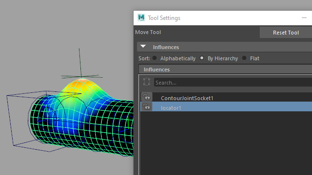
Figure 15
Areas where rigid influences are frequently used include heads, small influences like ears, buttons, armor, and other rigid parts of clothing. In some cases, like the bottoms of the feet, rigid influences can be used on one side of a spline to limit the spread and bend of the deformer only to areas where it benefits you.
Rigid influences are frequently parented to a Rig Tools Joint or constrained using the Rig Tools deform field constraint (below). Either of these options allows a Rig Tools joint chain to be used for animation without any additional layers of control.
Painting weights on the Rig Tools deformer
Painting weights on the Rig Tools deformer has been designed to be very similar to using the Maya interface. There is a list of influences (each either a deform field or a rigid influence) and each can be selected in order to perform the usual weight painting operations. The deformer will use a linear blend between the influences. Figure 16.
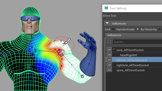
Figure 16
There are a few notable differences in how you will wanto to paint weights for a Rig Tools deformer, though. The first is that since most of the influences are usually entire Rig Tools deform fields, and each deform field is driven by several joints, the number of influences you need to paint is drastically reduced. The areas that require painting are limited to where the deform fields overlap, and generally the number of influences affecting any given vertex is also reduced.
In part this reduction in complexity comes from an adjustment in how you think about areas that deform heavily. In order to gain the benefits of the Rig Tools deform field, areas that would usually be affected by many influences are better off weighted entirely to a single influence.
The inclusion of overshoot joints (in areas such as the hips), makes painting weights in this manner possible. The overshoot joint on a hip is rigged to move with the spine. Since the Rig Tools spline runs through this area with an appropriate curvature, the hip benefits fully from the spread and volume preserving aspects of the deform field, and provides easy adjustment of the appearance with the deformer attributes when much of the weight in the regions of highest deformation is given to the leg chain. Figure 17.
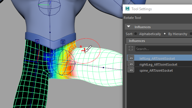
Figure 17
You may also note a small but pleasant difference when the weight painting tool tries to normalize weights after a paint stroke and can’t do so. Rather than normalize by including extraneous influences that had not previously affected the area, the deformer instead refuses to change the weight value if it can’t be normalized. This avoids situations where removing the last unlocked influence from a vertex would flood that point with a small value from every influence in the deformer, making weight values unpredictable.
Using the Rig Tools Component editor
Influence values can also be edited manually, using the Rig Tools Component Editor. To access this tool, choose Rig Tools ► Deform ► Component Editor, and select the vertices you wish to edit. The interface mirrors Mayas component editor and should be familiar. Select cells and enter the new values, select columns by clicking on the name of the influence and rows by the name of the vertex, etc. You can also lock and unlock influences, to prevent them being adjusted by normalization operations, by toggling the booleans in the top row.
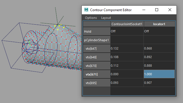
Figure 18
Copying and Mirroring weights
Weights can be mirrored within a mesh, mirrored between two meshes, and copied from one mesh to another in a straightforward manner. Both mirror and copy weights work by finding the closest point on a mesh in world space, so be sure to line your meshes up correctly before performing a mirror or copy.
To mirror influence weights within a mesh, select your mesh and choose Rig Tools ► Deform ► Mirror Weights. To mirror influence weights from one mesh to another, select the source mesh followed by the destination mesh, then choose Rig Tools ► Deform ► Mirror Weights.
Options for this tool include the axis to mirror across, the direction to mirror in, and method by which influences to be mirrored onto are associated with influences to be mirrored from. You can choose to associate influences by proximity or by name.
When mirroring weights by proximity, we first find the world-space position of each influence, mirrored across the mirror axis. We then match that influence with the influence whose world-space position is closest to that mirrored position. Note that this means that an influence can match itself when mirroring within a single mesh, as would be the case with, for instance, a spine. The world-space position of a Contour joint chain is the world-space position of its joint socket.
When mirroring weights by name the convention is that one side of your character is the right-hand side, and the other the left-hand side—which side is which is up to you. Mirroring will attempt to match influences with names that begin with “right_”, “right”, or “r_” with influences that begin with “left_”, “left” or “l_”, but are otherwise identical. The prefix matching is not case-sensitive (that is, “RIGHT” is treated as if it were “right”, etc.,) but the matching of the portion of the name after the prefix is. We do not limit prefix matching to prefixes of the same general form—that is, “right” will match “left_” or “l_”, as well as “left”. If this causes ambiguity—for instance if you have an influence named “right_hand” and influences named “left_hand” and “l_hand”—an error will be signalled. When mirroring within a single mesh, if an influence does not have a name with a prefix, or if no corresponding influence is found, the influence’s weights will be mirrored to itself. When mirroring weights from one mesh to another, all of the source mesh’s influences must have corresponding influences in the destination mesh, and source influences with no prefix must have an identically named destination influence.
To mirror weights onto just a portion of the mesh, create a Maya Set of vertices. Either select the Set to mirror weights within a single mesh, or select the source mesh and the Set to mirror weights from one mesh to another, and choose Rig Tools ► Deform ► Mirror weights from the menu.
To copy influence weights from one mesh to another, select the source mesh then the destination mesh and choose Rig Tools ► Deform ► Copy Weights. This tool has one option, which specifies how influences bound to the source mesh are associated with influences bound to the target mesh.
When copying weights by closest influence, each influence bound to the source mesh will be associated with the influence bound to the target mesh that is closest to it in world space. The world-space position of a Contour joint chain is the world-space position of its joint socket.
When copying weights by same influence, all influences bound to the source mesh must also be bound to the target mesh. Each influence will have its weights copied from the source mesh to the target mesh.
To copy influence weights onto a just a portion of a mesh, create a Maya Set of vertices. Select a mesh to copy from, and the set of vertices to copy to, and choose Rig Tools ► Deform ► Copy Weights.
Pruning weights
Rig Tools ► Deform ► Prune Small Weights will remove influences below the threshold from vertices, exactly like its Maya counterpart.
About Splines and Deform Fields
Every Rig Tools chain used in a deformer or constraint actually has two splines associated with it, an active spline and a bind spline. When animating, the two splines are compared and the difference between the two fields is what determines the deformation of the mesh. It’s possible to produce deformation by animating the bind spline as well, but every time the bind spline is changed, Rig Tools must rebind the mesh, which is a costly operation. Actions that would change the bind spline should be avoided when performance is an issue. By default, it is not connected to anything. Figure 19.
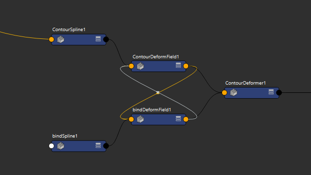
Figure 19
Rigid influences simply store a single transform matrix as their bind state, and do not have splines associated with them.
Scaling an entire Rig Tools spline
You can scale (including nonuniform scale) an entire spline and its deform field by scaling its joint socket. Figure 20.
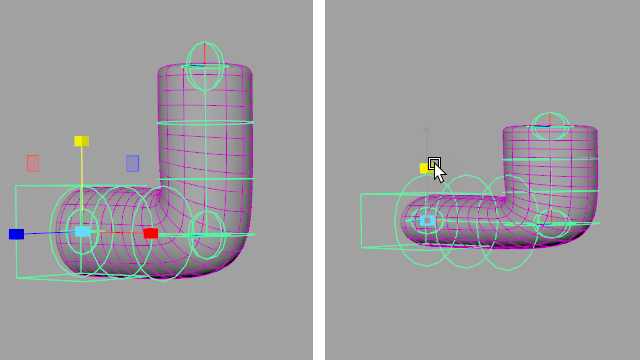
Figure 20
Driving Rig Tools Splines With Conventional Transforms
Our joints and bones are designed to output the information needed to drive Contour splines and deform fields, and our tools create the necessary connections automatically. Figure 21.
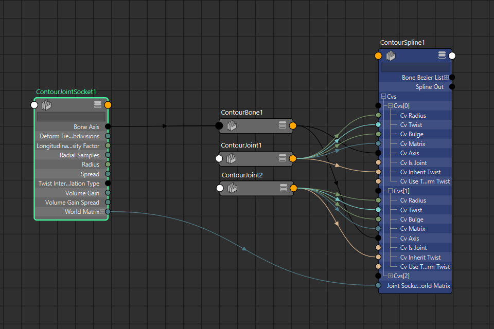
Figure 21
Advanced users may wish to use Contour’s splines and deformation without using Contour’s joints and bones. You can use conventional transforms to drive Contour splines by connecting the right attributes. Detailed instructions on how to do this are beyond the scope of this manual, but users experienced enough to want to create their own front-end to Contour deformation are likely to learn enough simply by looking at an existing Contour rig—we’ve tried to make the flow of data through Contour nodes as clean and easy to understand as possible.
If you’d like our assistance with setting up an alternative way of driving Contour deformation in your pipeline, please get in touch with us at business@notionalpipe.com
Constraints
Rig Tools includes two new constraint types that work with Rig Tools joint chains, the Deform Field Constraint and the Spline Constraint.
Rig Tools Constraint
The deform field constraint constrains a transform node to a Rig Tools deform field. The transform will translate and rotate exactly as if it were a mesh vertex deformed by the field. Because the transform is driven by the deform field that deforms the mesh, rather than by the mesh itself, it will match the mesh’s deformation regardless of its position relative to the mesh. Figure 1.
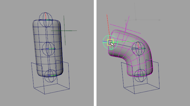
Figure 1
To add a deform field constraint, select the joint socket of the chain you wish to constrain to, then the transform to be constrained, and choose Rig Tools ► Tools ► Create Rig Tools Constraint from the menu.
The Rig Tools Constraint is useful in a number of situations, such as:
Driving items of clothing, such as buttons, or jewelry that lies close to the skin.
Adding adjustment controls to the rig. The constraint will ensure they move with the rest of the Rig Tools-deformed mesh.
Driving other Rig Tools nodes, for instance constraining a Rig Tools joint to a different Rig Tools chain. Constraining the hip overshoot joint to the spine is a common example.
Making simple muscle rigs by driving the beginning and end of a Rig Tools chain with two other chains, such as rigging the pectoral or latissimus dorsi muscles to stretch between the spine and arm.
Driving rigid joints with a Rig Tools deformer so you can take advantage of Rig Tools deformation in a situation where only conventional joints are viable, such as a game engine.
“Deforming” a character that is actually made up of lots of little pieces of geometry, like dragon scales. Figure 2.
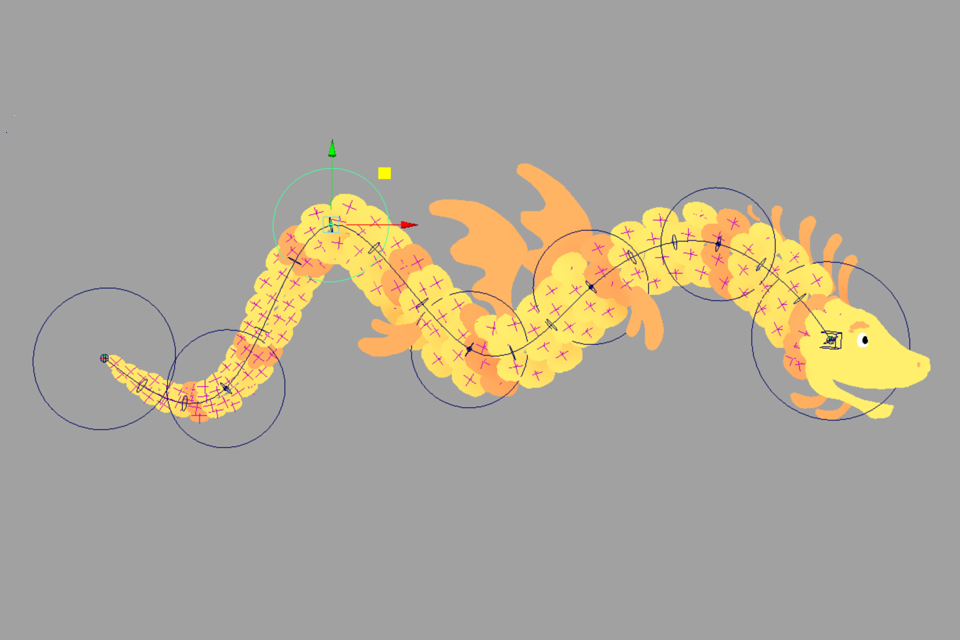
Figure 2
Spline Constraint
The Spline constraint attaches a transform directly to the spline. The transform will move with, orient along, and twist with the spline. Figure 3.
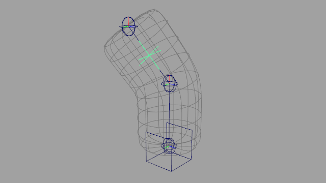
Figure 3
To add the constraint, first select the joint socket of the spline you wish to bind to, then a transform node, then choose Rig Tools ► Tools ► Create Rig Tools Spline Constraint. The transform will be moved to the closest point on the spline when the constraint is created.
The position of the transform along the arc length of the spline can be changed by adjusting the Parameter attribute. The Parameter is relative to the joints that drive the spline. 0 represents the position of the first joint, 1 the second, and so forth until the last joint. To constrain to a position halfway along the spline between the first and second joints, the parameter would be set to 0.5, to a position halfway between the second and third it would be set to 1.5, etc. Figure 4.
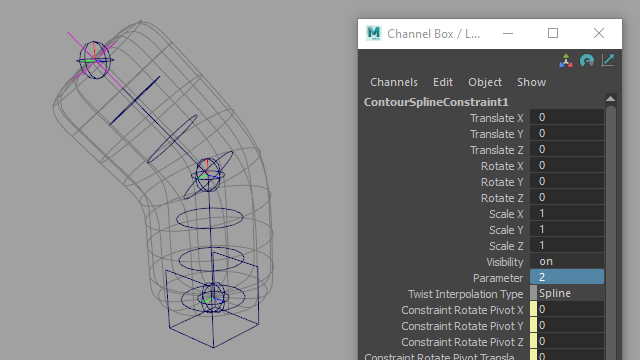
Figure 4
The Spline deformer is useful for cases where you want to drive conventional joints or transforms with the flexibility and control over twist of the Rig Tools spline, but don’t need the mesh spreading and volume gain of the deform field. This is also a very useful technique for creating engine-compatible rigs with Rig Tools.
For an example where the Rig Tools spline constraint is used to drive a Maya pose interpolator, see Using Rig Tools With Other Deformers.
Removing Constraints
Rig Tools constraints can be removed by selecting and deleting the constraint node.
Control Rigging
Rig Tools Joints as Controls
Rig Tools Joints are designed to function as both joints and animation controls, and in many cases additional FK control structures aren’t necessary. Joints and bone CVs are fully buffered—meaning that they are zeroed in their default position—and can be used directly as animation controls.
You can easily add a NURBs shape to a joint or bone CV for selection purposes. Select the joint and choose Rig Tools ► Bones ► Add Circle Shape from the menu. The circle size is based on the joint radius, and can be edited if another shape is desired. Figure 1.
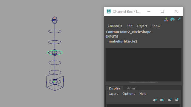
Figure 1
The Override Blend attribute of Rig Tools joints means that you can use a joint as an FK control, while blending to alternate inputs for other types of control. Rig Tools provides a number of additional control schemes that plug into the Override inputs: aim handles, IK handles, and Rig Tools orients.
Caveat for Animation Caching Maya 2019 and 2020 have a bug that causes custom transforms that calculate their own matrix, such as Rig Tools joints, bones, and bone CVs, to evaluate incorrectly during manipulation while animation caching is active. This issue is fixed in Maya 2022. If you intend to use a Rig Tools rig in Maya 2019 or 2020 with animation caching active, you won’t be able to animate the joints directly and will need to use a more conventional, separate set of controls for manipulation.
Aim Handles
The Rig Tools Aim Handle creates a locator at a Rig Tools joint that drives both the rotation of the previous joint and the stretch of the bone between the two joints. Translating the handle will rotate the chain to aim at the handle, while the stretch will ensure that the bone always reaches the handle. Since the handle is created directly on top of a joint, it is common to add a circle shape— by choosing Rig Tools ► Bones ► Add Circle Shape from the menu—to the handle after creation for ease of selection. Figure 2.
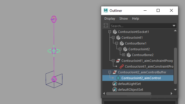
Figure 2
To create a Rig Tools Aim Handle, select any joint that is not the first joint in a chain and choose Rig Tools y► Tools ► Create Rig Tools Aim Handles from the menu. If multiple joints are selected, multiple handles will be created, each controlling one of the joints.
Aim handles have a Blend attribute, which drives the Override Blend of both the joint and the bone, so that it is easier to blend the aim on and off. This aim does not have an up-vector; if an up-vector is required see below.
Aim Handle with Up Vector
Similar to an Aim Handle, but a second locator will be generated to control the up vector of the handle, allowing additional control over the orientation of the joint. Figure 3.
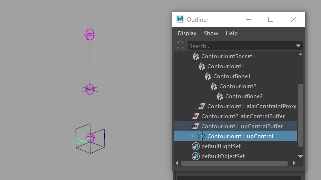
Figure 3
Deleting Aim Handles
To delete an aim handle, select the handle, and choose Contour Rig Tools ► Tools ► Delete Contour Aim Handle. The aim handle system must be connected in the fashion our tools connect aim handle systems when creating them. If you have changed any connections in the system it will not be deleted.
Deleting an aim handle does not delete its buffer.
IK Systems
The Rig Tools IK handle connects three joints in a chain using a rotate-plane IK solver. It can be used in conjunction with standard FK control of the joints, and includes a number of features commonly added to IK rig setups.
To create an Rig Tools IK handle, select three joints along a joint chain and choose Rig Tools ► Tools ► Create Rig Tools IK Handle from the menu. An IK handle and a pole vector locator will be created, and the joints and the bones between the joints will be connected to the handle using the appropriate override attributes on those nodes.
The features included in the Rig Tools IK handle are:
Orient of the last bone in the chain is controlled by the handle by default when the IK handle is created.
Automatic stretch to reach the handle (which can be toggled on or off) as well as individual stretch controls.
“Smooth stretch” optionally stretches the joint chain slightly when reaching its full extent to avoid IK pop.
Overrides rotation and stretch of the joints and bones instead of connecting directly to the transform attributes. Figure 4.
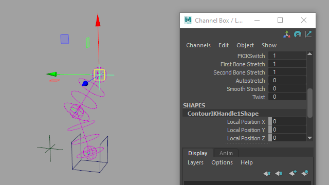
Figure 4
Deleting IK Systems
To delete an IK system, select its IK Handle, and choose Contour Rig Tools ► Tools ► Delete Contour IK Handle.
Rig Tools Orient
The Rig Tools Orient is a simple orient that uses Maya’s matrix nodes to drive rotation instead of a constraint. Like the aim and IK handles, it connects to a Rig Tools joint’s override rotation attributes instead of the standard transform attributes.
In addition to allowing you to add your own controls to the rig, the Rig Tools Orient is useful in conjunction with an Rig Tools aim constraint to drive the rotation of the end of the chain. For instance, at the top of the spine to drive the torso, or at the end of an arm to drive a hand. The Rig Tools IK handle automatically provides this functionality and does not need an additional constraint. Figure 5.
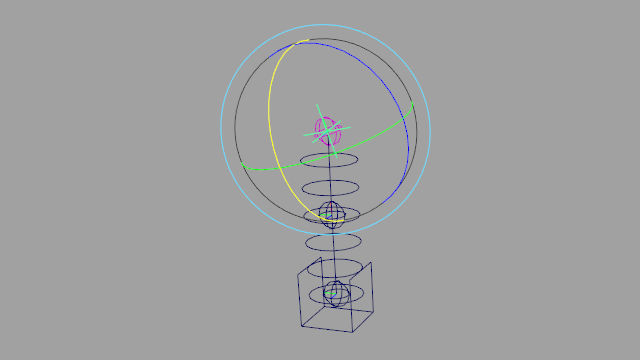
Figure 5
To create a Rig Tools Orient, select a transform node and then a Rig Tools joint, and choose Rig Tools ► Tools ► Create Rig Tools Orient from the menu. The rotation of the transform will drive the Override Rotation value of the Rig Tools Joint.
Deleting Orients
To delete an orient, select the joint that is being oriented, and choose Contour Rig Tools ► Tools ► Delete Contour Orient. The orient must be connected in the fashion our tools connect orients when creating them. If you have changed any connections in the system it will not be deleted.
Arbitrary control rigging
In addition to these Rig Tools features, you’re free to constrain or drive Rig Tools joints and Bone CVs in any way you’d drive a normal Maya transform. You could, for instance, use Rig Tools to handle the deformation of a mesh and drive it with an existing control rig just as you would a conventional Maya joint hierarchy.
Using Rig Tools With Other Deformers
Deformation order considerations
Rig tools works well with other Maya deformers, but there are some considerations that should be borne in mind. Putting other deformers underneath the Rig Tools deformer will require it to rebind whenever the deformers beneath it change. Binding is computationally expensive in version 1 of Rig Tools—we’d like to imporove its performance in a future release, but doing so is not trivial—and should therefore be avoided when possible. Instead, layer deformers on top of the Rig Tools deformation. Doing so has the additional advantage of allowing other deformers to go onto Maya’s GPU deformer stack—since Rig Tools is not yet a GPU deformer, anything beneath it in the deformer stack will not be executed on the GPU.
Blend Shapes
Blend shapes should be placed on top of the Rig Tools deformer whenever possible, using tangent or transform space blend shapes. See Maya’s documentation on tangent space and transform space blend shapes for more details. Figure 1
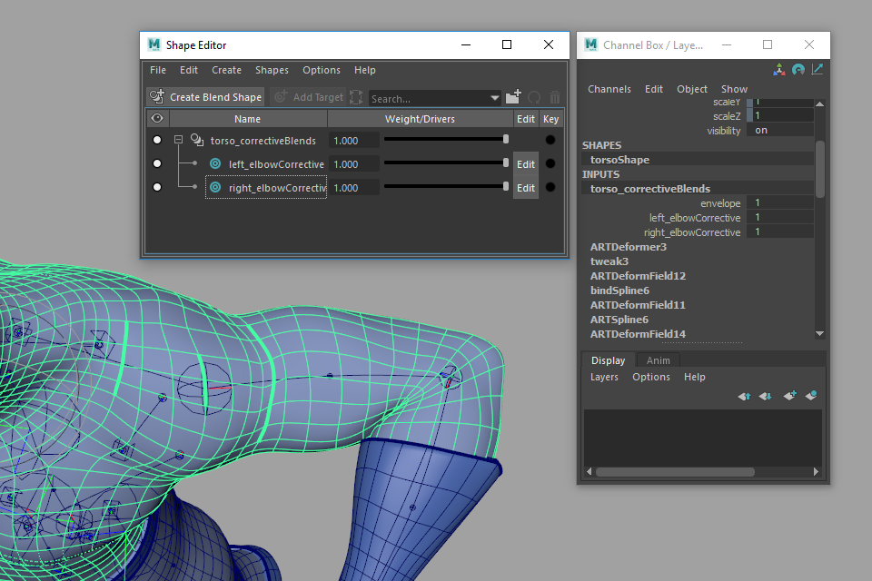
Figure 1
Transform space blend shapes tend to evaluate faster than tangent space blend shapes, and are more reliable, but Maya does not currently offer a tool to mirror them, requiring some custom scripting to use them effectively. Use whichever is most appropriate for your situation.
Layered skin clusters
It is often useful to layer a conventional Maya skin cluster on top of Rig Tools deformation to provide additive tweak controls. Figure 2
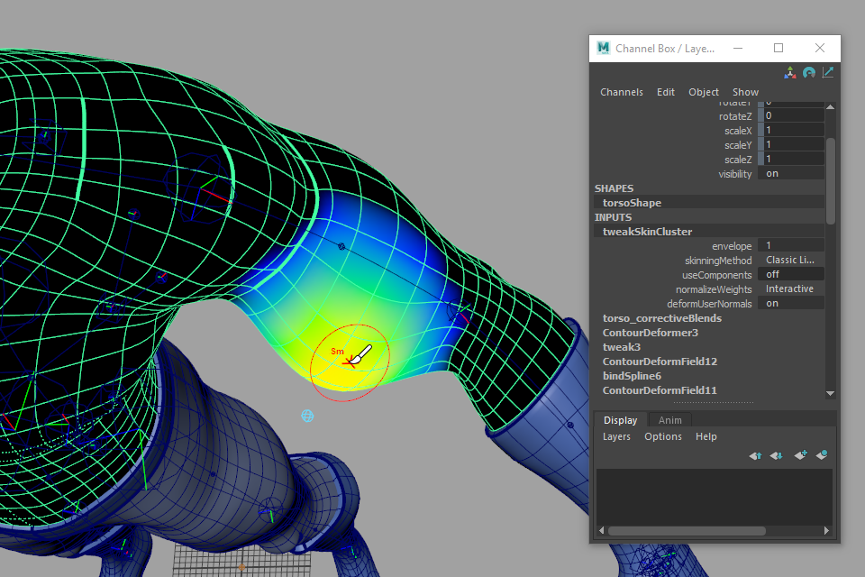
Figure 2
A common way to create tweak controls that ride along with the rig is to buffer a tweak joint, then constrain the buffer to the rig using a Contour Deform Field constraint. The bindPreMatrix attributes of the Maya skin cluster can be driven by the buffer, which allows the joint to move along with the rig without double transformation. Figure 3
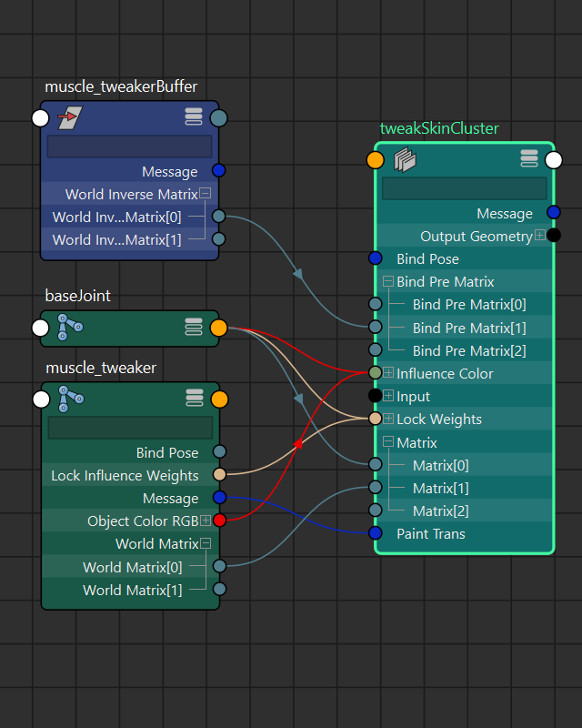
Figure 3
Pose Interpolators
Pose Interpolators (also called Pose Space Deformers, or PSDs) are a useful tool for achieving very specific deformation by driving a blend shape only when the the character assumes a specific pose. They are usually driven by the rotation of a transform, such as a joint.
Rig tools bones are splines, and can have bone CVs, so the rotation values of their associated joints do not fully determine their shape. We have included a tool to add spline constrained locators to the Rig Tools spline that can be used to drive a Maya Pose Interpolator correctly. To add these locators to your spline, select a joint and choose Rig Tools ► Tools ► Create Locators to Drive Maya PSD from the menu.
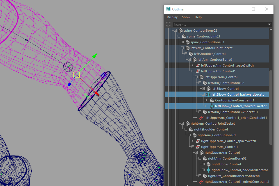
Figure 4
This will create two locators constrained to the spline on either side of the joint. The locator further down the chain (the forward locator) is parented to the one further up the chain (the backward locator), and should be used to drive the Pose Interpolator. The forward locator’s orientation in world space is the frame along the spline at that point along its length. Because it is parented to the backward locator, using the forward locator’s rotation to drive the Pose Interpolator is analogous to using a Maya joint’s rotation to drive a Pose Interpolator in a more conventional rig.
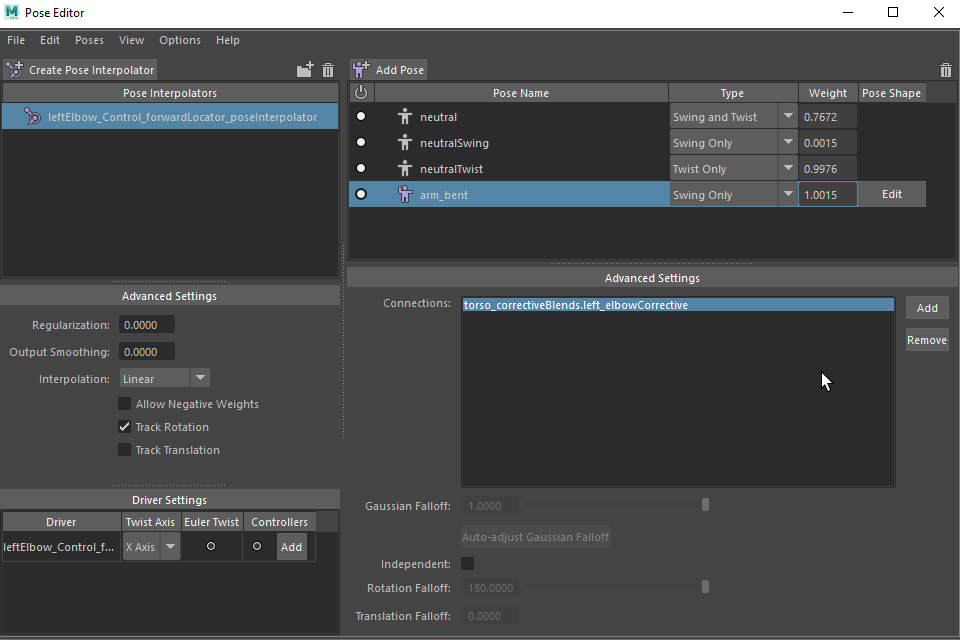
Figure 5
You can also use either the backward or forward locator as the transform for the transform space of a transform-space blend shape.
For more information on setting up Pose Interpolators and driving blend shapes with them, see Maya’s documentation.
Delta Mush Deformation
Delta Mush deformation is an excellent complement to Rig Tools, and is particularly useful for handling areas of relatively constant curvature at the transition between Rig Tools influences.
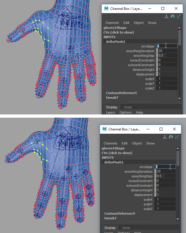
Figure 6
You will usually want to limit Delta Mush to areas where Rig Tools influences overlap. In areas controlled by one spline, Rig tools usually gives better results by itself. To limit the Delta Mush deformation to the appropriate areas you can apply a Delta Mush deformer to the entire mesh and paint away the parts you don’t want it to affect, or apply it just to a set of vertices.
Some examples of cases where Delta Mush is often useful are:
The skin between thumb and palm
The armpit
The side of the neck
The crotch
Techniques
Overshoot
Rig Tools’ spline-based deformation is driven by changes in the spline in the neighborhood of the point on the spline a vertex to be deformed is bound to. As a result, vertices bound to the very end of a Rig Tols spline do not gain the full benefits of Rig Tools deformation, and behave very much as if they were deformed by a normal Maya skin cluster and weighted entirely to a single influence at the very end of the spline.
Because of this, it is very common to extend Rig Tools joint chains past the point at which a Maya joint chain would stop, adding an extra joint, in order to bind vertices past that point to the interior of a spline, and create a sufficient “neighborhood” around their bind positions to provide control over their deformation. We call this “overshoot”, and it is a very useful technique for areas like hips, wrists, and ankles.
For example, in a simple Maya leg there might be three joints, one each at the hip, knee, and foot—for simplicity’s sake, we’ll ignore the toe for now. The hip joint is placed inside the body at the desired pivot, and its influence is weight painted to blend with the rest of the body. Figure 1

Figure 1
Creating weights that look good for a hip is difficult, and the Rig Tools deformer can do better, but it requires an extra joint to do so.
Because vertices bound to the end of a spline deform rigidly, if we were to start our chain where the hip joint would be in the Maya chain there would be nice Rig Tools deformation heading away from the first joint, but none passing through it. To ensure we have Rig Tools deformation at and around our hip, as well as deformation controls like joint radius, we need to start our chain with another joint, above the hip. With the hip joint in the interior of the chain, the vertices around it will all get nice Rig Tools deformation. Figure 2
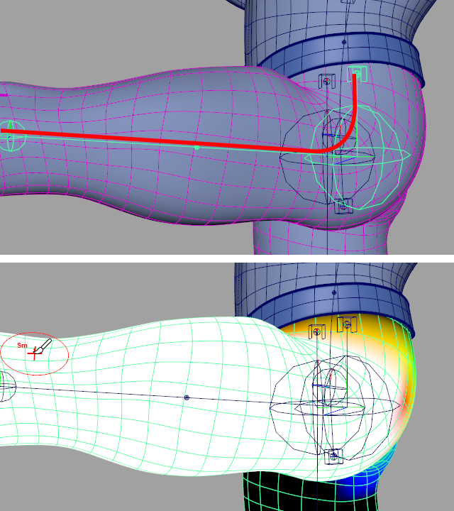
Figure 2
Of course, the hip overshoot joint also affects the shape of the spline, and the effect of the leg’s joint chain will have to be blended into that of the spine’s joint chain in the area above the hip. The easiest way to do this is to use a deform field constraint to constrain the overshoot joint to the spine. The deform field constraint constrains a transform so that it behaves as if it were deformed by the joint chain it is contrained to. With the hip overshoot joint constrained to the spine, you can start painting away the influence of the leg chain between the hip and the hip overshoot joint. Since the hip overshoot joint is moving with the spine, you are painting between two influences that are doing very similar things, which makes the blended region seamless. Figure 3
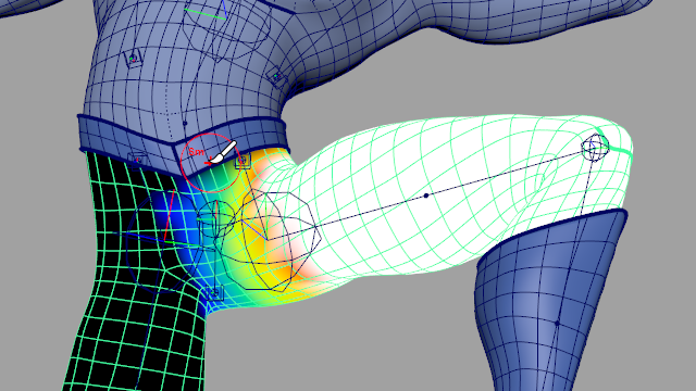
Figure 3
Overshoot is also useful at the end of a joint chain. In a simple Maya leg chain, the foot joint is an influence, and rotating it would deform the geometry of the foot. Rotating the last joint of a Rig Tools Chain does not rotate the geometry beyond it, because it is the spline that is actually driving the deformation, and the shape of the spline is determeined by the position of its control points—the Joints and Bone CVs in its joint chain. A spline’s control points do not have an orientation. Figure 4
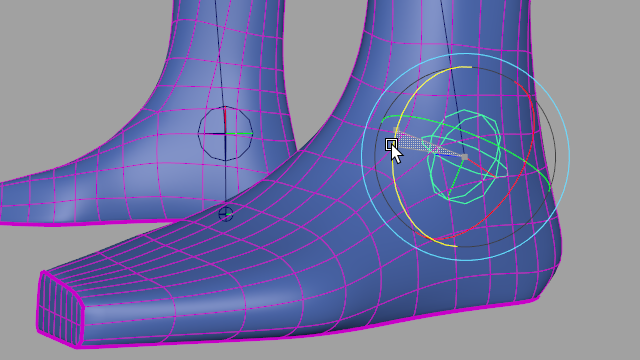
Figure 4
To make rotating the last joint of the chain behave as we would like, an additional joint must be added to the end of the chain. Figure 5
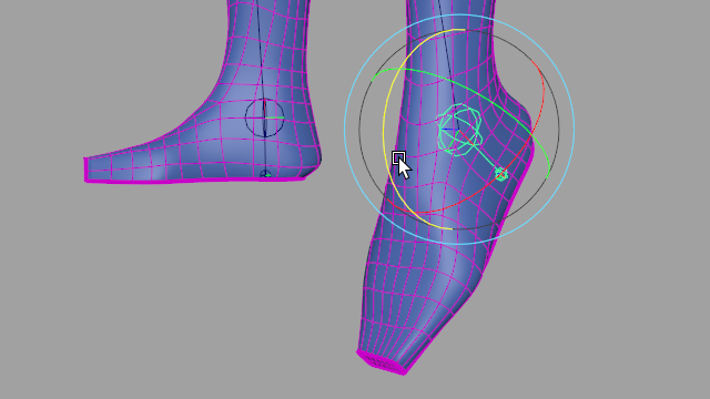
Figure 5
Deeciding how far from your main joints to place your overshoot joints can require some experimentation. We have found that a good rule of thumb is to consider where you want the mesh spread to stop—for instance, in the case of a wrist you generally want the palm to become rigid by the time the fingers start. Placing the overshoot joint very close to the joint it overshoots from can sometimes produce undesirable deformation, as the Rig Tools deformer is forced to “stabilize” the deformation immediately without a smooth transition. Figure 6
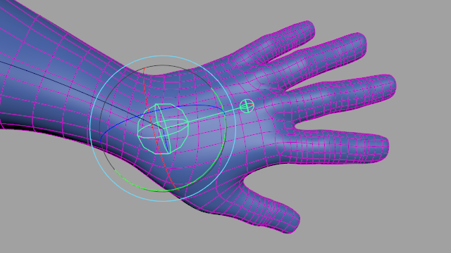
Figure 6
Simple muscles
When rigging characters with a well-defined physique, some kind of muscle-based deformation is often necessary. However, a fully simulated muscle deformation system is frequently overkill for nonphotorealistic characters. Rig Tools can be used to make simple muscle deformation that is very easy to set up.
To create a simple muscle system, add a one-bone joint chain across the area your muscle covers, and constrain the first and last joints of the chain to your character’s existing Rig Tools skeleton using Deform Field constraints. The muscle chain’s first and last joints will follow existing deformation very closely, but stretch and compress the area between them. Figure 7
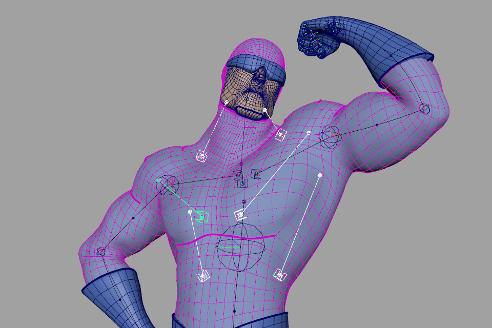
Figure 7
You can then simply paint appropriate areas of the mesh to this muscle chain. Figure 8
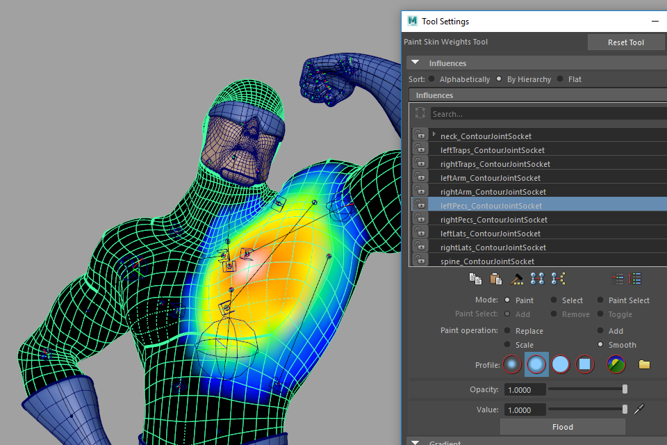
Figure 8
“Broken” or “free” rigging
When animating very cartoony characters, it is often expedient to skip FK/IK blending systems and the complexity that comes with them, and simply have the animator place the character’s limb controls—such as the elbows and knees—directly.
Doing this kind of “broken” rigging using Rig Tools is primarily a matter of using aim handles rather than IK handles for the character’s arms and legs. Other aspects of broken rigging (stretchy limbs, for instance) naturally follow from Rig Tool’s spline-based deformation. Figure 9
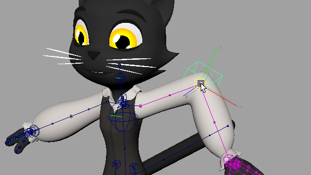
Figure 9
It’s often convenient for rigs like this to have some sort of “stretch meter” that tells the animator when they have stretched the character enough beyond its original dimensions to be off-model. Rig tools splines output their length as an attribute called Arc Length, which can be used to easily calculate how different a spline’s current length is from its bind length.
Transform-only deformation
Because both the deform field and spline constraints pick up all of the twist behavior present on a Rig Tools spline, they’re an excellent way to drive conventional joints and other transforms without introducing complex rig systems to manage multiple influences for twist and bend behavior. This is particularly useful for game engine export. Figure 10
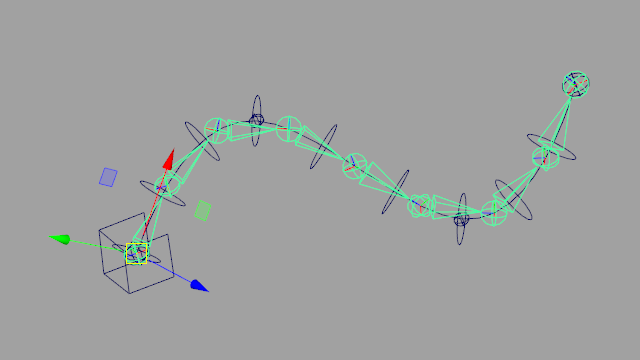
Figure 10
The Pre-deprecated API
What Do You Mean, Pre-Deprecated?
API design is famously difficult, and once an API has been made public it is bad form to make breaking changes to it. We want to provide an initial API that will allow users to do necessary scripting with Contour, but we also plan on creating a more comprehensive, and hopefully more elegant, API in the future. Pre-deprecated may be a bit of a misnomer—we plan to support this API indefinitely, and while we do not absolutely promise not to make breaking changes to it we will avoid doing so without a very compelling reason.
The pre-deprecated API is small, but provides what we think users will need to script Contour effectively. If you need functionality it doesn’t provide, please get in touch with us at support@notionalpipe.com. Because it might be some time before we introduce a newer API we plan on expanding this one as needed. There are also some useful internal functions that we can expose, though it is very likely that we will make breaking changes to those.
General Considerations
It is important to use our functions, where we have provided them, to create and delete our nodes, as the connections between joint chains, meshes, deformers, etc. are complicated and finicky. Creating nodes with incorrect connections, or deleting nodes without properly adjusting connections, is likely to lead to errors in graph evaluation.
Importing and Calling the API
The API’s namespace is Contourlib.predeprecatedAPI. So you could import the API and call one of its functions like this:
import Contourlib.predeprecatedAPI as api

api.createJointSocketAndJoint()
Arguments and Return Types
Data Types
API functions that take Maya nodes as arguments accept PyNodes, MObjects (either OM1 or OM2,) or the names of the nodes as strings. When passing the names of DAG nodes as strings, enough of the path to uniquely identify the node must be present in the name.
Functions that take geometric types, such as vectors, euler rotations, and quaternions, generally accept PyMEL data types from the pymel.core.dt namespace as well as OpenMaya data types.
API functions that return Maya nodes return them as PyNodes.
Referring to Joint Chains and Splines
API functions that take an argument that refers to a joint chain, or to the spline that joint chain generates, take the chain’s Joint Socket as an argument. Note that this applies when passing joint chains as influences to be bound to a Contour deformer.
Referring to Meshes
API functions that take a mesh as an argument accept either the mesh (as a PyNode, an MObject, or a string) or the Contour deformer that deforms the mesh (as a PyNode, an MObject, or a string.)
Exceptions
The API functions can throw a number of custom exceptions, documented in the descriptions of individual functions. Note that while we check for many exceptional situations it is also possible for the API functions to throw exceptions raised by code in Maya libraries called from those functions. All custom exceptions raised by API functions inherit from ContourScriptError. All custom exceptions that can be raised by the API come from the Contourlib.scripts.exceptions namespace.
Caveats
Creating and Deleting Contour Shape Nodes in a Single Cycle
Creating a Contour node that has a shape node, and then immediately deleting it within the same cycle, will cause the shape node to continue to be drawn when using Viewport 2.0. Saving and re-opening the scene will fix this, but to avoid it when scripting you can call the refresh function from the maya.cmds namespace or PyMEL between creating and deleting the node.
Creating, Deleting, and Duplicating Contour Joint Chains
- createJointSocketAndJoint(translation=pymel.core.dt.Vector.zero, rotation=pymel.core.dt.EulerRotation.identity, parent=None, jointSocketName=None, jointName=None, boneAxis='x')
Creates a joint socket and joint
- Parameters
translation – the world-space position of the joint socket, as a PyMEL vector, an OpenMaya vector, or a 3-tuple
rotation – the world-space rotation of the joint socket, as a PyMEL Euler rotation, a PyMEL quaternion, or a 3-tuple representing an Euler rotation
parent – the parent of the joint socket, as a name, a PyNode, an MObject, or None
jointSocketName – the name of the joint socket, or None to have the API assign a default name
jointName – the name of the joint, or None to have the API assign a default name
boneAxis – the bone axis of the joint chain, one of “x”, “y”, “z”, “-x”, “-y”, or “-z”
- Returns
a tuple containing the newly created joint socket and joint, i.e. (jointSocket, joint), as PyNodes
- Raises
ContourBadArgumentsError: Translation or rotation is not a value that can be used to set translation or rotation using the set function of a PyMEL PyAttribute, or parent is not a Maya node, or is not a transform, or boneAxis is not one of “x”, “y”, “z”, “-x”, “-y”, or “-z”.
- createJointInChain(previousJoint, boneLength=5.0, jointOrient=pymel.core.dt.EulerRotation.identity, jointName=None, boneName=None)
Creates a bone and a joint following previousJoint in the joint chain
- Parameters
previousJoint – the joint after which to create the new joint and bone, as a name, a PyNode, or an MObject
boneLength – the length of the bone to be created
jointOrient – the orientation of the joint, as a PyMEL Euler rotation, a PyMEL quaternion, a 3-tuple representing an Euler rotation, or None
jointName – the name of the joint, or None to have the API assign a default name
boneName – the name of the bone, or None to have the API assign a default name
- Returns
a tuple containing the newly created joint and bone, i.e. (joint, bone), as PyNodes
- Raises
ContourBadArgumentsError: previousJoint is not a maya node, or is not a ContourJoint.
ContourDegenerateSceneGraphError: The joint chain previousJoint belongs to is not correctly connected.
- deleteJointInChain(joint)
Deletes joint, its distal bone, and any bone CVs that apply to that bone. Adjusts as many as two proximal bones such that all distal joints and bones maintain their world position when the joint chain is in its zeroed out state.
- Parameters
joint – the joint to delete, as a name, a PyNode, or an MObject
- Returns
None
- Raises
ContourBadArgumentsError: Joint is not a Maya node, or is not a ContourJoint.
ContourDegenerateSceneGraphError: The joint chain joint belongs to is not correctly connected.
- createBoneCV(jointOrBoneCV)
Creates a bone CV after jointOrBoneCV
- Parameters
jointOrBoneCV – the joint or bone CV after which to create the new bone CV, as a name, a PyNode, or an MObject
- Returns
the newly created bone CV, as a PyNode
- Raises
ContourBadArgumentsError: jointOrBoneCV is not a Maya node, or is not a ContourJoint or a ContourBoneCV.
ContourDegenerateSceneGraphError: The joint chain jointOrBoneCV belongs to is not correctly connected
- deleteBoneCV(boneCV)
Deletes boneCV
- Parameters
boneCV – the bone CV to delete, as a name, a PyNode, or an MObject
- Returns
None
- Raises
ContourBadArgumentsError: boneCV is not a Maya node, or is not a ContourBoneCV
ContourDegenerateSceneGraphError: The joint chain boneCV belongs to is not correctly connected.
- duplicateJointChain(jointSocket)
Duplicates jointSocket, its bone chain, and any descendant bone chains. Returns the newly created joint socket corresponding to jointSocket.
- Parameters
jointSocket – the joint socket of the joint chain to be duplicated, as a name, a PyNode, or an MObject
- Returns
the joint socket at the root of the newly created chain, as a PyNode
- Raises
ContourBadArgumentsError: jointSocket is not a Maya node, or is not a ContourJointSocket.
ContourDegenerateSceneGraphError: The joint chain jointSocket belongs to is not correctly connected.
Creating Contour Constraints
- createDeformFieldConstraint(jointSocket, transform)
Given a joint socket and a transform node, creates a Contour constraint that constrains the transform to the joint chain
- Parameters
jointSocket – the joint socket of the joint chain to constrain to, as a name, a PyNode, or an MObject
transform – the transform to be constrained, as a name, a PyNode, or an MObject
- Returns
the newly created constraint, as a PyNode
- Raises
ContourBadArgumentsError: jointSocket is not a Maya node, or is not a ContourJointSocket, or transform is not a Maya node, or is not a transform.
ContourDegenerateSceneGraphError: The joint chain jointSocket belongs to is not correctly connected.
ContourUnbindableInfluenceError: The joint chain jointSocket belongs to contains only one joint, and cannot be constrained to.
- createSplineConstraint(jointSocket, transform)
Given a joint socket and a transform node, creates a Contour Spline constraint that constrains the transform to the Contour spline corresponding to the joint socket
- Parameters
jointSocket – the joint socket of the spline to constrain to, as a name, a PyNode, or an MObject
transform – the transform to be constrained, as a name, a PyNode, or an MObject
- Returns
the newly created constraint, as a PyNode
- Raises
ContourBadArgumentsError: jointSocket is not a Maya node, or is not a ContourJointSocket, or transform is not a Maya node, or is not a transform.
ContourDegenerateSceneGraphError: The joint chain jointSocket belongs to is not correctly connected.
ContourNoSplineError: The joint chain jointSocket belongs to contains only one joint and cannot be constrained to.
ContourDegenerateSplineError: The joint chain jointSocket belongs to is connected to a Contour spline node that does not correctly output a spline.
Creating and Deleting Contour IK Systems
- createIKSystem(firstTransform, secondTransform, thirdTransform, ikHandle=None, poleVector=None, useOverride=True, createConstraint=True, allowUnstretchableTransforms)
Creates an IK system from three transforms and an optional ik handle and pole vector
- Parameters
firstTransform – the first transform of the system (e.g. a shoulder), as a name, a PyNode, or an MObject. This can be any transform other than a Maya joint.
secondTransform – the second transform of the system (e.g. an elbow), as a name, a PyNode, or an MObject. This can be any transform other than a Maya joint.
thirdTransform – the third transform of the system (e.g. a hand or wrist), as a name, a PyNode, or an MObject. This can be any transform other than a Maya joint.
ikHandle – the node to be used as the IK handle of the system, as a name, a PyNode, or an MObject, or None to create a new locator
poleVector – the node to be used as the pole vector of the system, as a name, a PyNode, or an MObject, or None to create a new locator
useOverride – if True, connects the IK system to the overrideRotation attributes of the first two transforms, instead of the rotation attribute, if they are CountourJoints
createConstraint – if True, constrains the third transform to the IK handle using an orient constraint
allowUnstretchableTransforms – If False, a ContourIKUnstretchableTransformError will be raised if the IK system would contain transforms that might break autostretch. If True, the IK system will be created even in their presence. See the Raises section for details.
- Returns
a tuple containing the IK handle, the pole vector, and the ContourIKSolver node, as PyNodes
- Raises
ContourBadArgumentsError: Any of firstTransform, secondTransform, thirdTransform, poleVector, or IKHandle is not a Maya node, or is not a transform, or firstTransform, secondTransform, or thirdTransform is a Maya joint.
ContourIKNodeNotConnectableError: Any of the attributes that would be connected when making the IK system is not connectable.
ContourIKUnstretchableTransformError: The IK system would contain transforms other than Contour bones that have translation, the system would have autostretch, and allowUnstretchableTransforms is False.
ContourIKHierarchyError: secondTransform is not a descendant of firstTransform, thirdTransform is not a descendant of secondTransform, or ikHandle or poleVector is a descendant of firstTransform.
ContourIKCollinearityError: firstTransform, secondTranform, and thirdTransform are collinear.
- deleteIKSystem(IKHandleOrSolver)
Deletes an IK system’s handle, pole vector, and solver, given its IK handle or solver
- Parameters
IKHandleOrSolver – The IK Handle or IK Solver of the IK system to be deleted, as a name, a PyNode, or an MObject. If a node that is the IK Handle of more than one IK system is passed as this argument, all of the systems it is the IK Handle of will be deleted.
- Returns
None
- Raises
ContourBadArgumentsError: IKHandleOrSolver is not the IK handle or solver of a Contour IK system.
Creating and Deleting Aim Handles
- createAimHandle(joint, upVector=None)
Added in Contour Rig Tools v1.0.6.1
Creates an aim handle for a Contour Joint.
- Parameters
joint – the joint to create an aim handle for, as a name, a PyNode, or an MObject. Joint must have a ContourBone somewhere above it in the DAG hierarchy.
upVector – if truthy, an upVector will be created
- Returns
a tuple of the newly created aim handle and the up vector, as PyNodes. If an up vector was not created, None will be returned for the up vector.
- Raises
ContourBadArgumentsError: joint is not a ContourJoint, or joint does not have a ContourBone somewhere above it in the DAG hierarchy ContourMayaPluginNotFoundError: The “matrixNodes” plug-in could not be loaded. Creation of aim handles requires that the “matrixNodes” plug-in, which ships with Maya, be loaded. We attempt to load it if is not loaded. This exception is thrown if it cannot be loaded.
- deleteAimHandle(handle)
Added in Contour Rig Tools v1.0.6.1
Deletes an aim handle, and associated nodes, with the exception of the buffers. The aim system must be connected “canonically”– that is, as our tools connect it when creating aim handles and their systems. If the system’s connections have been altered an exception will be raised, and the system will not be deleted.
- Parameters
handle – the handle of the aim system to be deleted, as a name, a PyNode, or an MObject.
- Returns
None
- Raises
ContourBadArgumentsError: handle is not an aim handle associated with a canonically connected aim system.
Creating and Deleting Orients
- createOrient(driver, targetJoint)
Added in Contour Rig Tools v1.0.6.1
Creates an orient for a Contour Joint.
- Parameters
driver – the transform whose world-space orientation the targetJoint will take on, as a name, a PyNode, or an MObject.
targetJoint – The Contour Joint to be oriented
- Returns
a tuple containing driver and targetJoint, as PyNodes
- Raises
ContourBadArgumentsError: Driver is not a transform, or targetJoint is not a Contour Joint.
ContourMayaPluginNotFoundError: The “matrixNodes” plug-in could not be loaded. Creation of orients requires that the “matrixNodes” plug-in, which ships with Maya, be loaded. We attempt to load it if is not loaded. This exception is thrown if it cannot be loaded.
- deleteOrient(joint)
Added in Contour Rig Tools v1.0.6.1
Deletes a Contour Orient. The orient must be connected “canonically”– that is, as our tools connect it when creating orients. If the orient’s connections have been altered an exception will be raised, and the orient will not be deleted.
- Parameters
handle – the Contour Joint associated with the orient to be deleted, as a name, a PyNode, or an MObject.
- Returns
None
- Raises
ContourBadArgumentsError: joint is not a Contour Joint associated with a canonically connected orient.
Binding, Rebinding, and Unbinding
- bindMeshToDeformer(mesh, influences, bindDescendantChains=False)
Binds influences to mesh, creating a new ContourDeformer
- Parameters
mesh – the mesh to bind, or its transform, as a name, a PyNode, or an MObject
influences – the influences to bind, as an iterable of names, PyNodes, or MObjects If an influence is a joint socket, its Contour chain will be bound. Chains with zero radius and chains with only one joint cannot be bound. Contour nodes other than joint sockets cannot be bound. Any transform that is not a Contour node will be bound as a rigid influence.
bindDescendantChains – if truthy, will also bind all Contour joint chains that are descendants of any of the influences. Added in v1.0.7
- Returns
the newly created deformer, as a PyNode
- Raises
ContourBadArgumentsError: The mesh or at least one of the influences is not a Maya node, or mesh is not a mesh or the transform of a single mesh.
ContourMeshAlreadyBoundError: mesh is already bound to a Contour deformer.
ContourMultipleMeshesError: mesh is a transform node that has more than one mesh shape.
ContourRepeatedInfluenceError: An influence appears more than once in influences.
ContourUnbindableInfluenceError: An influence could not be bound for one of the following reasons:
Only transforms can be bound.
Contour nodes other than joint sockets cannot be bound.
A joint chain with less than two joints, or with zero radius, cannot be bound.
- resetBind(influenceOrSpline)
Resets the bind position of the joint chain associated with a joint socket or spline to its current position, or resets the bind position of a rigid influence to its current position
- Parameters
influenceOrSpline – a bound Contour spline, a bound Contour joint socket, or a transform bound to a Contour deformer as a rigid influence, as a name, a PyNode, or an MObject. If node is a joint socket or spline, resets the bind position of the corresponding Contour joint chain. If node is a rigid influence, resets the bind position of the influence to its current position.
- Returns
None
- Raises
ContourBadArgumentsError: influenceOrSpline is not a Maya node, or is not either a rigid influence of a Contour deformer, or a joint socket or Contour spline that is an influence of a Contour deformer or a deform field constraint.
ContourDegenerateSceneGraphError: A joint socket or spline was passed as influenceOrSpline, and its scene graph is not correctly connected.
- addInfluencesToDeformer(meshOrDeformer, influences)
Adds influences to a ContourDeformer
- Parameters
meshOrDeformer – either the deformer to add influences to, or the mesh deformed by it, as a name, a PyNode, or an MObject
influences – the influences to add, as an iterable of names, PyNodes, or MObjects. If an influence is a joint socket, its Contour chain will be added. Chains with zero radius and chains with only one joint cannot be added. Contour nodes other than joint sockets cannot be added. Any transform that is not a Contour node will be added as a rigid influence.
- Returns
None
- Raises
ContourBadArgumentsError: meshOrDeformer or at least one of member of influences is not a Maya node, or meshOrDeformer is not a mesh, the transform of a single mesh, or a ContourDeformer.
ContourRepeatedInfluenceError: An influence appears more than once in influences.
ContourUnbindableInfluenceError: An influence could not be added for one of the following reasons:
Only transforms can be added.
Contour nodes other than joint sockets cannot be added.
A joint chain with less than two joints, or with zero radius, cannot be added.
An influence that is already bound to the deformer cannot be added.
- removeInfluencesFromDeformer(meshOrDeformer, influences)
Removes influences from a ContourDeformer
- Parameters
meshOrDeformer – either the deformer to remove influences from, or the mesh or mesh’s transform, as a name, a PyNode, or an MObject
influences – the influences to remove, as an iterable of names, PyNodes, or MObjects
- Returns
None
- Raises
ContourBadArgumentsError: meshOrDeformer or at least one member of influences is not a Maya node, or meshOrDeformer is not a mesh, the transform of a single mesh, or a Contour deformer, or a member of influences is not an influence of the deformer.
ContourRepeatedInfluenceError: An influence appears more than once in influences.
Contour Deformer Weights
- getWeightsUsingInfluenceIndices(meshOrDeformer, vertexIndices=None, influenceIndices=None)
Returns weight values for meshOrDeformer, with influences specified by index. If vertexIndices is not supplied, returns weight values for all vertices, otherwise returns only weights for the given vertex indices. If influenceIndices is not supplied, returns weight values for all influences.
- Parameters
meshOrDeformer – either the deformer to get weights from, or the mesh or mesh’s transform, as a name, a PyNode, or an MObject
vertexIndices – the indices of the vertices for which to get weights, as an iterable of integers, or None to get weights for all vertices
influenceIndices – the indices of the influences for which to get weights, as an iterable of integers, or None to get weights for all influences
- Returns
a dictionary of dictionaries, the outer keyed on vertex index, the inner on influence index, with the values of the inner dictionary the weights
- Raises
ContourBadArgumentsError: meshOrDeformer is not a Maya node, or meshOrDeformer is not a mesh, the transform of a single mesh, or a ContourDeformer, or vertexIndices or influenceIndices is not an iterable or contains invalid indices.
- getWeightsUsingInfluenceNames(meshOrDeformer, vertexIndices=None, influences=None)
Returns weight values for meshOrDeformer, with influences specified by name. If vertexIndices is not supplied, returns weight values for all vertices, otherwise returns only weights for the given vertex indices. If influenceNames is not supplied, returns weight values for all influences.
- Parameters
meshOrDeformer – either the deformer to get weights for, or the mesh or mesh’s transform, as a name, a PyNode, or an MObject
vertexIndices – the indices of the vertices for which to get weights, as an iterable of integers, or None to get weights for all vertices
influences – the names of the influences for which to get weights, as an iterable of strings, or None to get weights for all influences
- Returns
a dictionary of dictionaries, the outer keyed on vertex index, the inner on influence name, with the values of the inner dictionary the weights
- Raises
ContourBadArgumentsError: meshOrDeformer is not a Maya node, or meshOrDeformer is not a mesh, the transform of a single mesh, or a ContourDeformer, or vertexIndices or influenceIndices is not an iterable, or vertexIndices contains invalid indices, or influenceNames contains invalid names.
- setWeights(meshOrDeformer, weights, normalize=True)
Sets weights on meshOrDeformer. Weights is a dictionary keyed on vertex index. Its values are dicts keyed on either influence names or influence indices, but not both, whose values are weights. The format setWeights accepts is the same as that returned by getWeightsUsingInfluenceIndices.
- Parameters
meshOrDeformer – either the deformer to get weights for, or the mesh or mesh’s transform, as a name, a PyNode, or an MObject
weights – a dictionary keyed on vertex index, its values dicts keyed on either influence names, or influence indices, but not both, whose values are weights
normalize – if truthy, the weights will be normalized after being set
- Returns
None
- Raises
ContourBadArgumentsError: meshOrDeformer is not a Maya node, or meshOrDeformer is not a mesh, the transform of a single mesh, or a ContourDeformer, or weights contains keys that are not valid vertex indices or the values of weights contain keys that are not valid influence indices or influence names, or the values of weights contain both influence names and influence indices as keys.
TypeError: a weight value is not an integer, a floating point number, or something that can be coerced to a floating point number.
- copyWeights(sourceMeshOrDeformer, targetMeshOrDeformer, association='closest_influence', destVertices=None)
Copies weights for a ContourDeformer from sourceMeshOrDeformer to targetMeshOrDeformer
- Parameters
sourceMeshOrDeformer – either the deformer to copy weights from, or the mesh or mesh’s transform, as a name, a PyNode, or an MObject
targetMeshOrDeformer – either the deformer to copy weights to, or the mesh or mesh’s transform, as a name, a PyNode, or an MObject
association – The method used to associate influences of the source and target deformers; one of “closest_influence” or “same_influence”. If “closest_influence”, each source influence will be associated with the closest target influence, in world space. If “same_influence”, each influence of the source deformer must be an influence of the target deformer, and the association will be made by identity.
destVertices – An iterable of vertex indices or PyMel MeshVertex instances indicating the vertices of the destination mesh to copy to. If None, all vertices on the destination mesh will be copied to. Defaults to None.
- Returns
None
- Raises
ContourBadArgumentsError: sourceMeshOrDeformer or targetMeshOrDeformer is not a Maya node, or is not a mesh, the transform of a single mesh, or a ContourDeformer, or association is not one of “closest_influence” or “same_influence”, , or destVertices is not either None, or an iterable of vertex indices or PyMel MeshVertexIndices, or destVertices contains vertices that do not belong to targetMeshOrDeformer.
ContourNoCorrespondingInfluenceError: If association is “closest_influence”, either the source deformer or the target deformer has no influences. If association is “same_influence”, at least one influence of the source deformer is not an influence of the target deformer.
- mirrorWeights(meshOrDeformer, axis='x', negativeToPositive=False, association='closest_influence', destVertices=None)
Mirrors deformer weights across axis
- Parameters
sourceMeshOrDeformer – either the deformer to mirror weights for, or the mesh or mesh’s transform, as a name, a PyNode, or an MObject
axis – The world axis to mirror weights across. One of “x”, “y”, or “z”.
negativeToPositive – If truthy, mirrors weights from the negative side of the axis to the positive. Otherwise, mirrors from the positive side of the axis to the negative.
association – The method used to associate influences when mirroring. One of “closest_influence” or “equivalent_name”. If “closest_influence”, each influence will be associated with the influence closest to its position mirrored across axis (which could be the influence itself). If “equivalent_name”, each of the deformer’s influences whose names begin with “right_”, “right”, or “r_” will be associated with an influence that begins with “left_”, “left”, or “l_”, if both names, when stripped of their prefixes are the same, and vice versa. If an influence does not have a name with a prefix, or if no corresponding influence is found, the influence’s weights will be mirrored to itself. If an influence could be associated with more than one other influence, for instance, if there is an influence named “right_arm”, and influences named “left_arm” and “l_arm”, ContourAmbiguousNameAssociationError will be raised.
destVertices – An iterable of vertex indices or PyMel MeshVertex instances indicating the vertices of the destination mesh to copy to. If None, all vertices on the destination mesh will be copied to. Defaults to None.
- Returns
None
- Raises
ContourBadArgumentsError: meshOrDeformer is not a Maya node, or is not a mesh, the transform of a single mesh, or a ContourDeformer, or axis is not one of “x”, “y”, or “z”, or association is not one of “closest_influence” or “equivalent_name”, or destVertices contains vertices that do not belong to meshOrDeformer.
ContourNoCorrespondingInfluenceError: The deformer has no influences.
ContourAmbiguousNameAssociationError: association is “equivalent_name” and an influence could be associated with more than one other influence, e.g. there is an influence named “right_arm”, and influences named “left_arm” and “l_arm”.
- mirrorWeightsBetweenMeshes(sourceMeshOrDeformer, targetMeshOrDeformer, axis='x', negativeToPositive=False, association='closest_influence', destVertices=None)
Added in Contour Rig Tools v1.0.8
Mirrors deformer weights across axis between two meshes
- Parameters
sourceMeshOrDeformer – either the deformer to mirror weights from, or the corresponding mesh or mesh’s transform, as a name, a PyNode, or an MObject
targetMeshOrDeformer – either the deformer to mirror weights to, or the corresponding mesh or mesh’s transform, as a name, a PyNode, or an MObject
axis – The world axis to mirror weights across. One of “x”, “y”, or “z”.
negativeToPositive – If truthy, mirrors weights from the negative side of the axis to the positive. Otherwise, mirrors from the positive side of the axis to the negative.
association – The method used to associate influences when mirroring. One of “closest_influence” or “equivalent_name”. If “closest_influence”, each of sourceMeshOrDeformer’s influences will be associated with the influence of targetMeshOrDeformer closest to its position mirrored across axis. If “equivalent_name”, each of sourceMeshOrDeformer’s influences whose names begin with “right_”, “right”, or “r_” will be associated with an influence of targetMeshOrDeformer that begins with “left_”, “left”, or “l_”, if both names, when stripped of their prefixes, are the same, and vice versa. If an influence of sourceMeshOrDeformer does not have a name with a prefix, it will be matched with an influence of targetMeshOrDeformer with the same name. If an influence of sourceMeshOrDeformer could be associated with more than one influence of targetMeshOrDeformer, for instance, if sourceMeshOrDeformer has an influence named “right_arm”, and targetMeshOrDeformer has influences named “left_arm” and “l_arm”, ContourAmbiguousNameAssociationError will be raised.
destVertices – An iterable of vertex indices or PyMel MeshVertex instances indicating the vertices of the destination mesh to copy to. If None, all vertices on the destination mesh will be copied to. Defaults to None.
- Returns
None
- Raises
ContourBadArgumentsError: one of sourceMeshOrDeformer or targetMeshOrDeformer is not a Maya node, or is not a mesh, the transform of a single mesh, or a ContourDeformer, or axis is not one of “x”, “y”, or “z”, or association is not one of “closest_influence” or “equivalent_name”, or destVertices contains vertices that do not belong to targetMeshOrDeformer.
ContourNoCorrespondingInfluenceError: Either sourceMeshOrDeformer or targetMeshOrDeformer has no influences, or association is “equivalent_name” and sourceMeshOrDeformer has an influence that cannot be matched with an influence on targetMeshOrDeformer
ContourAmbiguousNameAssociationError: association is “equivalent_name” and an influence of sourceMeshOrDeformer could be associated with more than one influence of targetMeshOrDeformer, e.g. sourceMeshOrDeformer has an influence named “right_arm”, and targetMeshOrDeformer has influences named “left_arm” and “l_arm”.
- pruneSmallWeights(meshOrDeformer, threshold=0.01)
Prunes weights from mesh that are smaller than threshold, and normalizes. Small weights for vertices that cannot be normalized (for instance, because there are no unheld influences with non-zero weights) will not be pruned.
- Parameters
meshOrDeformer – the deformer for which to prune small weights, or the mesh deformed by it, as a name, a PyNode, or an MObject
threshold – a number; all weights smaller than this value will be pruned
- Returns
None
- Raises
ContourBadArgumentsError: meshOrDeformer is not a Maya node, or is not a mesh, the transform of a single mesh, or a ContourDeformer, or vertices does not contain only vertex indices and PyMel MeshVertex instances, or vertices contains MeshVertex instances that do not belong to the correct mesh.
- weightHammer(meshOrDeformer, vertices)
Given a mesh and an iterable of vertices, represented either by vertex indices or a PyMEL MeshVertex, sets each vertex’s weight to the average of the weights of its connected vertices
- Parameters
meshOrDeformer – either the deformer to hammer weights for, or the mesh or mesh’s transform, as a name, a PyNode, or an MObject
vertices – an iterable of vertex indices or PyMel MeshVertex instances
- Returns
None
- Raises
ContourBadArgumentsError: meshOrDeformer is not a Maya node, or is not a mesh, the transform of a single mesh, or a ContourDeformer, or vertices does not contain only vertex indices and PyMEL MeshVertex instances, or vertices contains MeshVertex instances that do not belong to the correct mesh.
Caveats
Because Contour Rig Tools does some things in ways that are non-standard for Maya, there are a few caveats that you’ll need to bear in mind when using Maya’s tools with Contour.
Maya 2023.0 and 2023.1
We only officially support the most recent update of each Maya version, but Contour will often work with older updates. However, Contour does not work in Maya 2023.0 and 2023.1. If you are running Maya 2023, please make sure you’ve updated to version 2023.2 or later.
Overrides and constraints
Constraining to a joint with rotation overrides
Rig Tools joints, bones, and bone CVs are all custom transforms that calculate their own matrices. This allows features like Override Rotation, where instead of using the rotate values from the transform’s rotate attribute, the joint uses a different set of rotation inputs to calculate its matrix. This greatly simplifies some aspects of rigging.
This does, however, introduce an additional complexity—Maya’s constraints do not use the matrix of the transform constrained to (which is generated using the input values), but instead uses the values of the transform’s rotation attribute. So if you constrain to a Rig Tools joint, the constraint will use the rotation values present in the channel box, not the joint’s actual rotation.
In Maya 2020 and later, the simplest solution is to avoid constraints and use matrix nodes instead, plugging the result into the target node’s Offset Parent Matrix attribute. For users who are using earlier versions of Maya, or who aren’t familiar with Maya’s new matrix-based rigging workflow, there are a couple of simple workarounds.
One option is to constrain to a null that has been parented to the joint, instead of constraining to the joint itself.
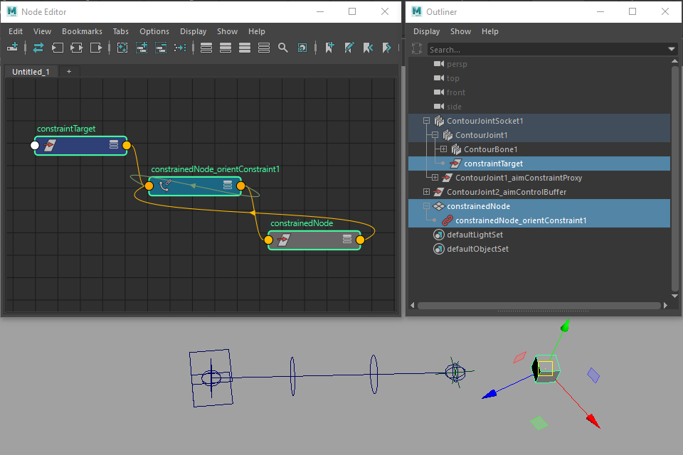
Figure 1
This workaround is easy to set up, but adds an additional transform to the rig. A slightly more complex solution is to pipe the joint’s matrix into a decomposeMatrix node to extract its actual rotation. This rotation value can be plugged into a constraint, or used to drive the rotation of another node directly.
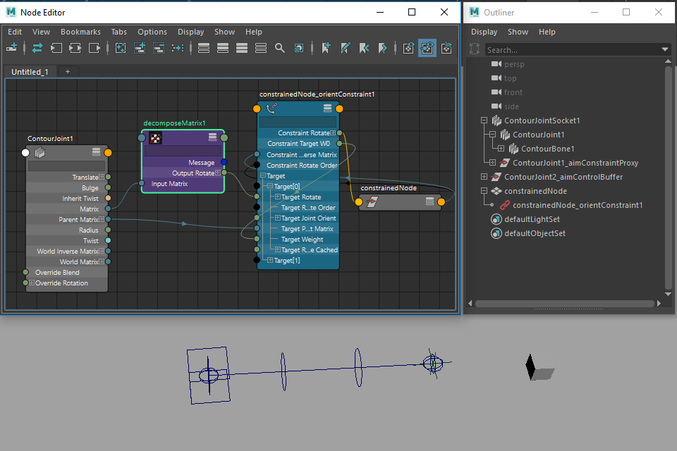
Figure 2
Connecting the output of a constraint into Override Rotation
Override Rotation is normally used to receive rotation values from Rig Tools IK systems, but you can drive it with any other source of rotation values. However, driving the Override Rotation attribute with the output of a Maya constraint causes Maya’s cycle check to incorrectly identify the result as a circularity. Since you don’t get the same error when connecting the output to the joint’s rotation attribute (which would be just as circular), this appears to be a problem with Maya’s cycle check.
To work around this, just create a null in the same parent space as the joint, constrain it normally, and connect its rotation to the joint’s Override Rotation attribute. This has the same effect, but does not cause a cycle check error.
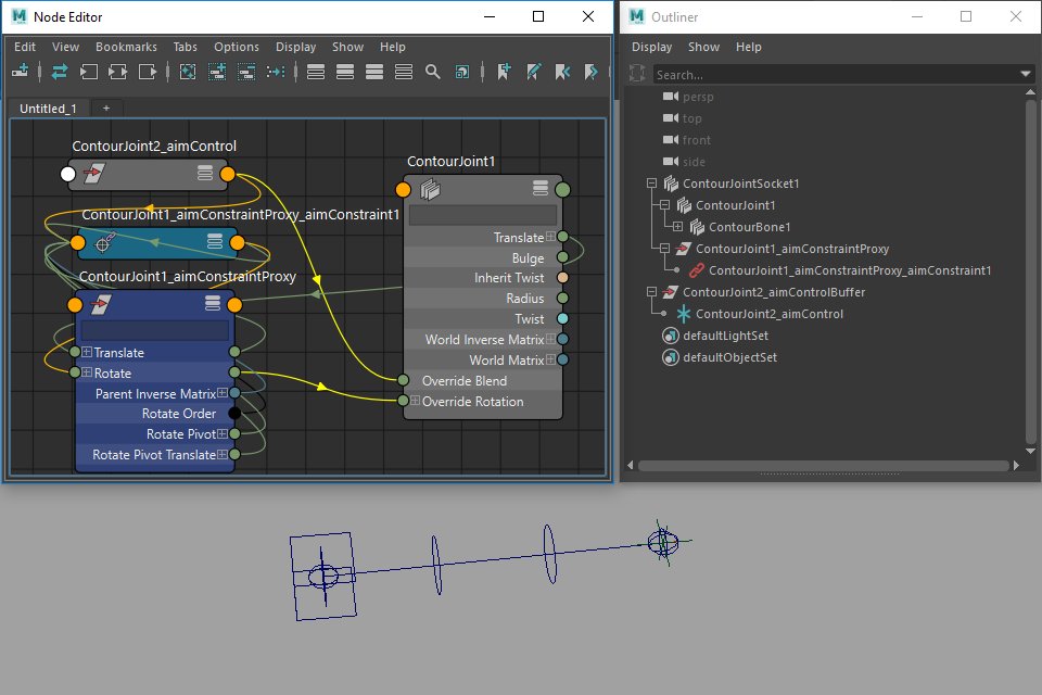
Figure 3
Optimizing Performance
Removing and restoring Rig Tools shapes
Due to issues with how viewport 2.0 handles custom locators, the shapes we use to make Rig Tools joints and bones visible to the user can have a significant impact on viewport draw performance when many are present. This occurs even when the shapes are not visible.
You can choose Contour Rig Tools ► Bones ► Delete All Contour Shape Nodes and Contour Rig Tools ► Bones ► Restore All Contour Shape Nodes from the menu to remove and restore Rig Tools shape nodes as needed. A common workflow is to work with shapes in place when rigging, and remove them when publishing a new version of the rig to animators. Any Rig Tools transforms that are being used as controls should have a NURBs shape added to them so that animators can still select them.
Putting Rig Tools deformation at the bottom of the deformation stack
Like many deformers—wraps and wires for instance—Rig Tools becomes much slower if it must rebind on every cycle. The most common scenario that requires rebinding is the mesh changing in some fashion before the Rig Tools deformer in the deformer stack. For best performance, we recommend putting all other deformers above the Rig Tools deformer. This means using post-deformation rather then pre-deformation blend shapes, for instance.
Reducing the density of the deform field
Rig Tools automatically decides on a density at which to sample the deform field based on the spline’s length and radius. However, in some circumstances—if a spline is perfectly straight and will never bend, for instance—reducing the density of the deform field can improve performance without significantly reducing the quality of deformation. The Longitudinal Density Factor and Radial Samples attributes present on the Joint Socket allow you to adjust the deform field’s density.
Longitudinal Density Factor controls how dense the deform field is down the spline. It defaults to 1, and is a multiplier of the density automatically chosen by rig tools—numbers greater than one create a denser field than the default, while numbers less than one create a less dense field. Radial Samples is not a multiplier, instead directly setting the number of samples taken radially around the spline. It defaults to 8.
These settings should be changed with caution, as values other than the default may produce undesirable deformation.